Wall system with vapor barrier securement

a technology of vapor barrier and wall, which is applied in the field of metal buildings, can solve the problems of affecting reducing the service life of vapor retarders, so as to reduce the risk of water vapor migrating, reduce the risk of vapor migrating, and minimize the effect of water vapor migration

Active Publication Date: 2014-11-11
BLUESCOPE BUILDINGS NORTH AMERICA
View PDF20 Cites 3 Cited by
  • Summary
  • Abstract
  • Description
  • Claims
  • Application Information

AI Technical Summary

Benefits of technology

[0006]A typical pre-engineered building wall consists of an outer exposed surface (wall panel), then insulation (blanket or board), and then a vapor retarder (on the interior, conditioned, side of the wall) which can consist of insulation facing, flexible membrane, metal liner (or panels) or other hard interior wall substrates with a good perm rating to minimize water vapor from migrating through it. The problem with the vapor retarder is where it joins up at locations where the building structure causes a break in the continuation of the barrier. This joint must be as tight as the vapor retarder material to maintain the continuation of the barrier. The disclosed technology provides a method to easily seal the joints of the vapor retarder at the structural column lines.
[0007]The disclosed technology installs the girts outside of the column line and eliminates this issue of compressing the insulation. Also, a trim piece is installed on the outside flange of the column to provide a surface to seal the vapor retarder from one side of the column to the other side. This trim extends the full height of the column to make contact with the roof vapor retarder therefore providing an integral roof vapor retarder.
[0008]It is critically important to maintain a continuous vapor retarder in the wall construction of a pre-engineered building and to have it tie to the roof vapor retarder so a continuous, monolithic vapor retarder occurs between the roof and wall. Without this monolithic, continuous vapor retarder, anywhere there is a void condensation or moisture can occur due to the relative humidity of the interior air reaching a surface that is at the dew point temperature. By maintaining a barrier, that is insulated to keep its temperature higher than the dew point temperature, condensation and moisture will avoided.
[0009]The typical wall and structural construction of a pre-engineered metal building creates numerous challenges that make it difficult to maintain a continuous vapor retarder throughout the wall and then tie it to the vapor retarder in the roof plane. The disclosed system, method and kit eliminates one of the major obstacles at each structural column line. The disclosed technology also provides for an area where economical blanket insulation can be installed in significant thickness with numerous exterior and interior wall configurations to make it very versatile for all kinds of wall systems. The purpose is to provide the high “R-value” wall system with a very good vapor retarder solution, and to provide this in a very easy to install method for the installer of the wall.

Problems solved by technology

With various webs, flanges and stiffeners needed at the column it makes it very difficult to fully insulate and utilize a continuous vapor retarder.
The problem with the vapor retarder is where it joins up at locations where the building structure causes a break in the continuation of the barrier.
The typical wall and structural construction of a pre-engineered metal building creates numerous challenges that make it difficult to maintain a continuous vapor retarder throughout the wall and then tie it to the vapor retarder in the roof plane.

Method used


Image

  • Wall system with vapor barrier securement
  • Wall system with vapor barrier securement
  • Wall system with vapor barrier securement

Examples


Embodiment Construction

[0017]Before describing the instant invention in detail, several terms used in the context of the disclosed technology will be defined. In addition to these terms, others may be defined elsewhere in the specification, as necessary. Unless otherwise expressly defined herein, terms of art used in this specification will have their art-recognized meanings.

[0018]Girt: a horizontal structural member in a framed wall that provides lateral support to the wall panel, primarily, to resist winds loads.

[0019]Wall line: the outermost perimeter of the wall of a building.

[0020]Perm rating: a measure of the diffusion of water through a material.

[0021]Vapor retarder: a vapor retarder is defined by ASTM Standard C 755 as a material or system that adequately retards the transmission of water vapor under specified conditions.

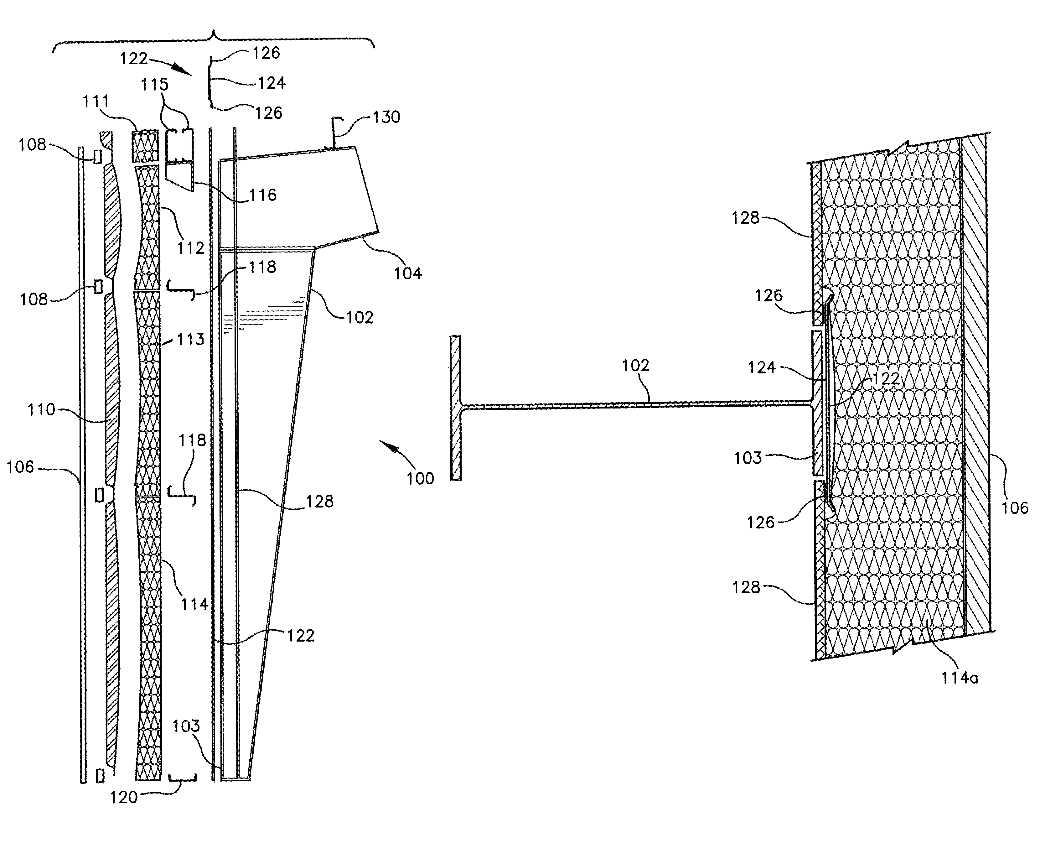
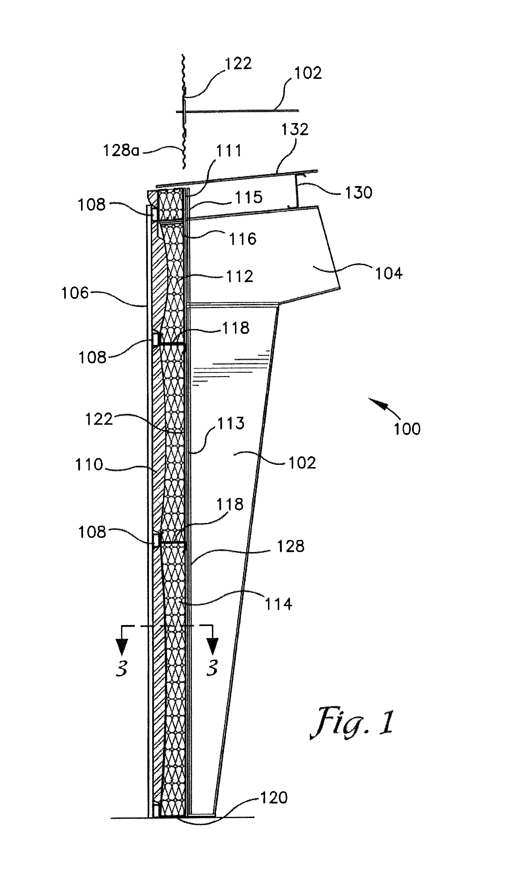
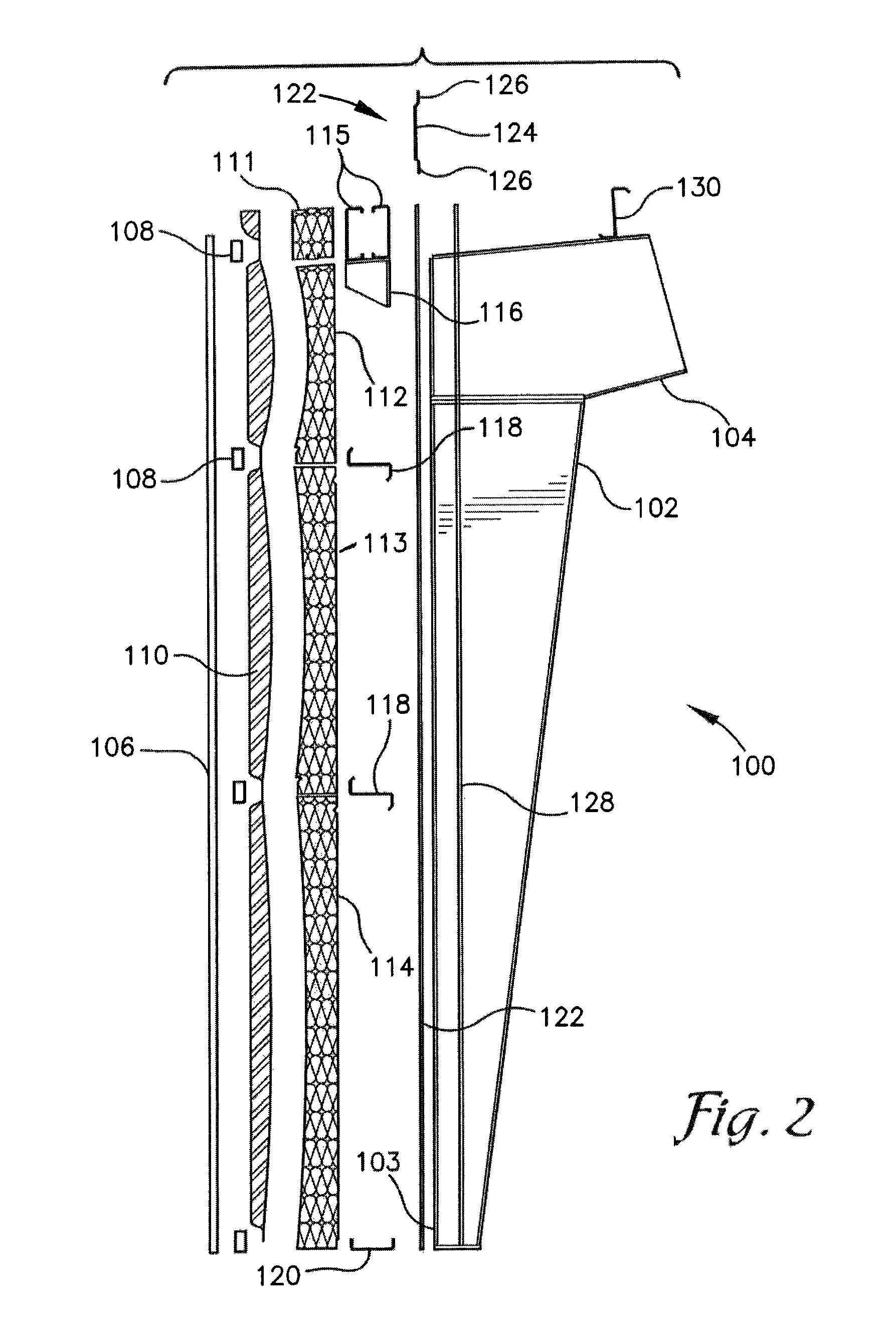
[0022]Embodiments of the disclosed technology provide a system, a kit and a method for establishing an insulated wall for a building.

[0023]Embodiments of the disclosed invention a...


PUM


Abstract

A system for assembling a pre-engineered building with a monolithic vapor retarder to control the formation of condensation on the walls. The system allows for numerous different combinations of insulation thickness, different kinds of walls, inside vapor retarders in different rigid panels, different facings or membranes. The system further provides for finished inside surfaces with high thermal quality.

Description

CROSS-REFERENCE TO RELATED APPLICATIONS[0001]This application claims the benefit of priority to U.S. Provisional Application No. 61 / 681,355 filed on Aug. 9, 2012.BACKGROUND OF THE INVENTION[0002]1. Field of the Invention[0003]The invention relates generally to the field of metal buildings. More specifically, the invention relates to the field of insulating a building and maintaining a vapor barrier in a wall of the building.[0004]2. Description of the Related Art[0005]Walls are typically supported horizontally by girts attached to columns constituting bays within the building structure. Typically the girts attach into the sides of the columns with the column located near the wall / girt attachment line. This method causes the typical wall insulation and vapor retarder to terminate into the side of the column. With various webs, flanges and stiffeners needed at the column it makes it very difficult to fully insulate and utilize a continuous vapor retarder. Also, by locating the column ...

Claims


Application Information

Patent Timeline
Patent Type & Authority Patents(United States)
IPC IPC(8): E04B1/66E04B1/24E04B1/74E04H5/10
CPCE04B2001/2481E04B1/66E04H5/10E04B2001/2487E04B1/24E04F13/081E04F13/12E04B1/18E04B1/80
Inventor MCCLURE, RICHARD, R.
Owner BLUESCOPE BUILDINGS NORTH AMERICA
Why Eureka
Try Eureka