Specimen holder for clamping workpieces

Active Publication Date: 2014-11-11
ZWICKROELL GMBH & CO KG
View PDF5 Cites 2 Cited by
  • Summary
  • Abstract
  • Description
  • Claims
  • Application Information

AI Technical Summary

Benefits of technology

[0004]The object of this invention is to create a test-specimen holder of the above-described type in such a way as to ensure that the grabs close symm

Problems solved by technology

Due to the test specimen geometry, however, it is frequently not

Method used


Image

  • Specimen holder for clamping workpieces
  • Specimen holder for clamping workpieces
  • Specimen holder for clamping workpieces

Examples


Example

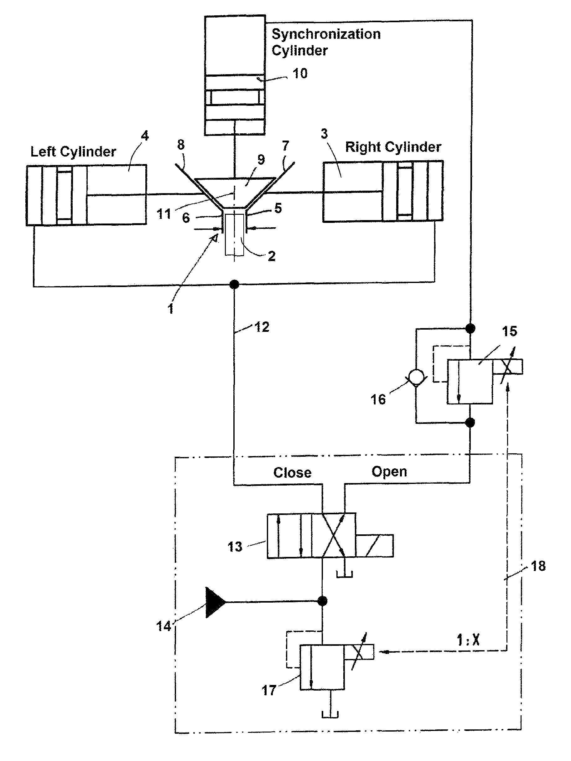
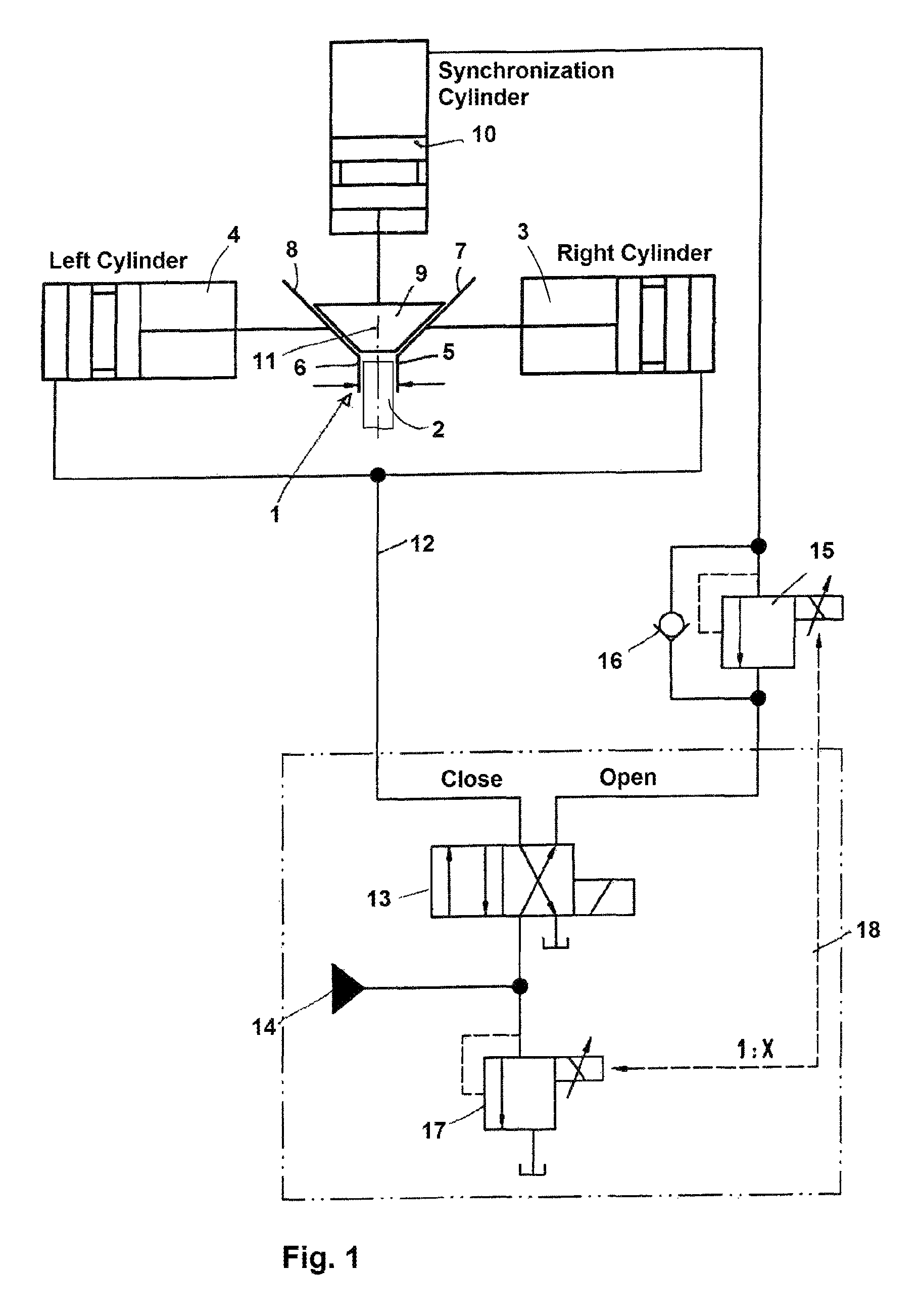
[0017]The test-specimen holder 1 shown in particular in FIG. 1 functions to grip test specimens 2 to allow component and material tests to be performed in the form of compression and in particular tensile tests.

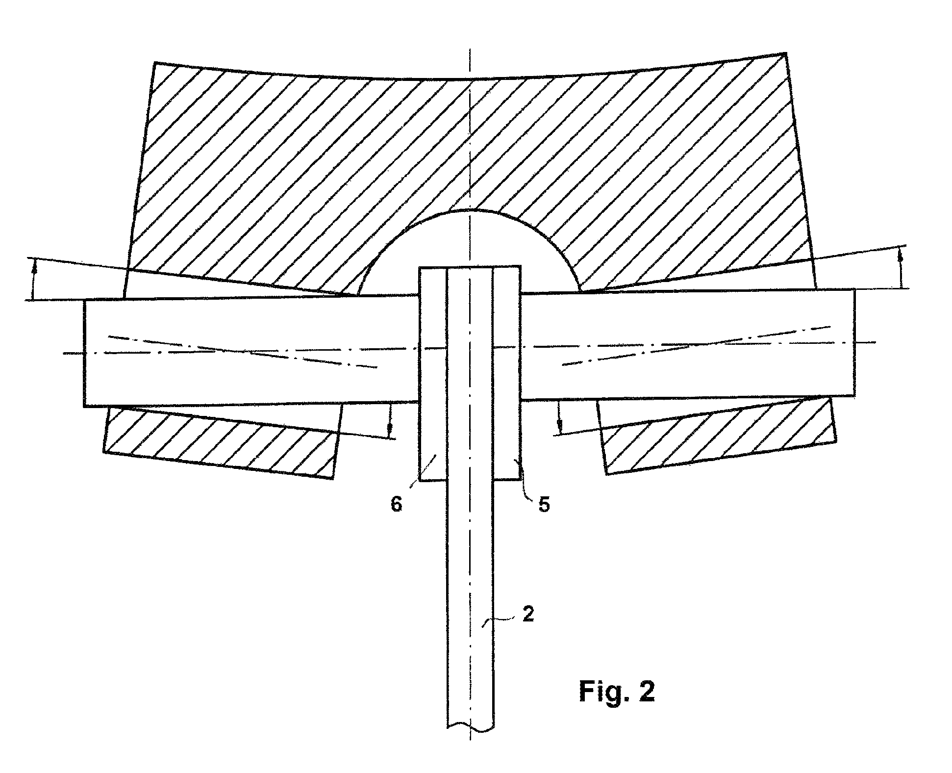
[0018]To this end, the test-specimen holder 1 has two grabs 5 and 6 that are preferably movable by respective hydraulic gripping cylinders 3 and 4 and are oriented coaxially relative to each other to grip the test specimen 2 between them.

[0019]On their sides facing away from the test specimen, the grabs 5 and 6 have respective angled faces 7 and 8 that contact a wedge 9. This wedge 9 is also movable perpendicular to the axis of the grabs by a similarly fluid-operated synchronization cylinder 10 and thus toward a test axis 11 of the test specimen 2.

[0020]The hydraulic equipment, which is described in detail below and is shown in FIG. 1, ensures that the wedge 9 and grabs 5 and 6 generally remain in mutual contact. This means that the wedge 9 returns back toward the synchroniza...


PUM


Abstract

A test-specimen holder for gripping test specimens to perform material tests in the form of compressive and tensile tests has two grabs coaxially aligned relative to each other and capable of gripping the test specimen. The grabs have angled faces on sides facing away from the test specimen gripped between them. Respective hydraulic gripping cylinders are connected to the grabs for shifting same axially and a wedge can engage the angled faces of both grabs. A fluid-operated synchronization cylinder is connected to the wedge for moving the wedge perpendicular to the axis of the grabs into and out of engagement with the angled faces of the grabs. A fluid reservoir is connected through a 4/2 directional control valve with the gripping cylinders for actuating same. An adjustable first pressure-limiting valve and a check valve connected parallel thereto are connected between the 4/2 valve and the synchronization cylinder.

Description

CROSS REFERENCE TO RELATED APPLICATIONS[0001]This application is the US-national stage of PCT application PCT / DE2010 / 000640 filed 4 Jun. 2010, published 10 Feb. 2011 as WO2011 / 015167, and claiming the priority of German patent application 102009036246.0 itself filed 5 Aug. 2009.BACKGROUND OF THE INVENTION[0002]The invention relates to a test-specimen holder for gripping test specimens, in particular, in order to perform material tests in the form of compressive and in particular tensile tests, comprising two grabs that are preferably movable by hydraulic gripping cylinders, are coaxially aligned relative to each other, and grip the test specimen between the grabs.[0003]When test specimens are gripped that are subsequently intended to undergo tensile tests, in particular, it is first of all critical to chuck them on center, that is, on the actual measurement axis, and, second, the test specimens should be chucked over a sufficient length between the grabs so as to prevent as much as ...

Claims


Application Information

Patent Timeline
IPC IPC(8): G01N3/04B23B31/16B23B31/177G01N3/02
CPCB23B31/16287B23B31/16254G01N2203/0017G01N3/04
Inventor GANSER, FRANZ
Owner ZWICKROELL GMBH & CO KG
Why Eureka
Try Eureka