Retractable safety gate

a safety gate and retractable technology, applied in the direction of safety guards, doors/windows, shutters/movable grilles, etc., can solve problems such as abrasion force, and achieve the effect of simplifying the structur

Active Publication Date: 2014-11-11
WANG TSUNG HSIANG
View PDF8 Cites 19 Cited by
  • Summary
  • Abstract
  • Description
  • Claims
  • Application Information

AI Technical Summary

Benefits of technology

[0010]The main objective of the present invention is to provide a retractable safety gate that has a simplified structure.
[0011]The retractable safety gate has a mounting assembly, a control assembly, a delaying assembly, an operating assembly, a blocking cloth, a grip assembly and a receiving assembly. The control assembly has a controller, a ratchet unit and a spiral spring. The spiral spring is connected between the controller and the ratchet unit. Thus, the controller is pulled back to the original position to be closed by the spiral spring, thereby reducing number of the components such that the retractable safety gate of the present invention has a simplified structure.
[0013]Therefore, when the accelerating gear assembly rotates the driving unit, the resistant units rotate relative to the driving unit by a centrifugal force. Accordingly the resistant units may abut against the resistant loop on the inside wall of the resistant cover, thereby generating an abrasion force. The abrasion force slows down the recovering movement of the controller. As a result, the resistance assembly can achieve the same function as a torsion spring, with reduced and simplified components.

Problems solved by technology

Accordingly the resistant units may abut against the resistant loop on the inside wall of the resistant cover, thereby generating an abrasion force.

Method used


Image

  • Retractable safety gate
  • Retractable safety gate
  • Retractable safety gate

Examples


Embodiment Construction

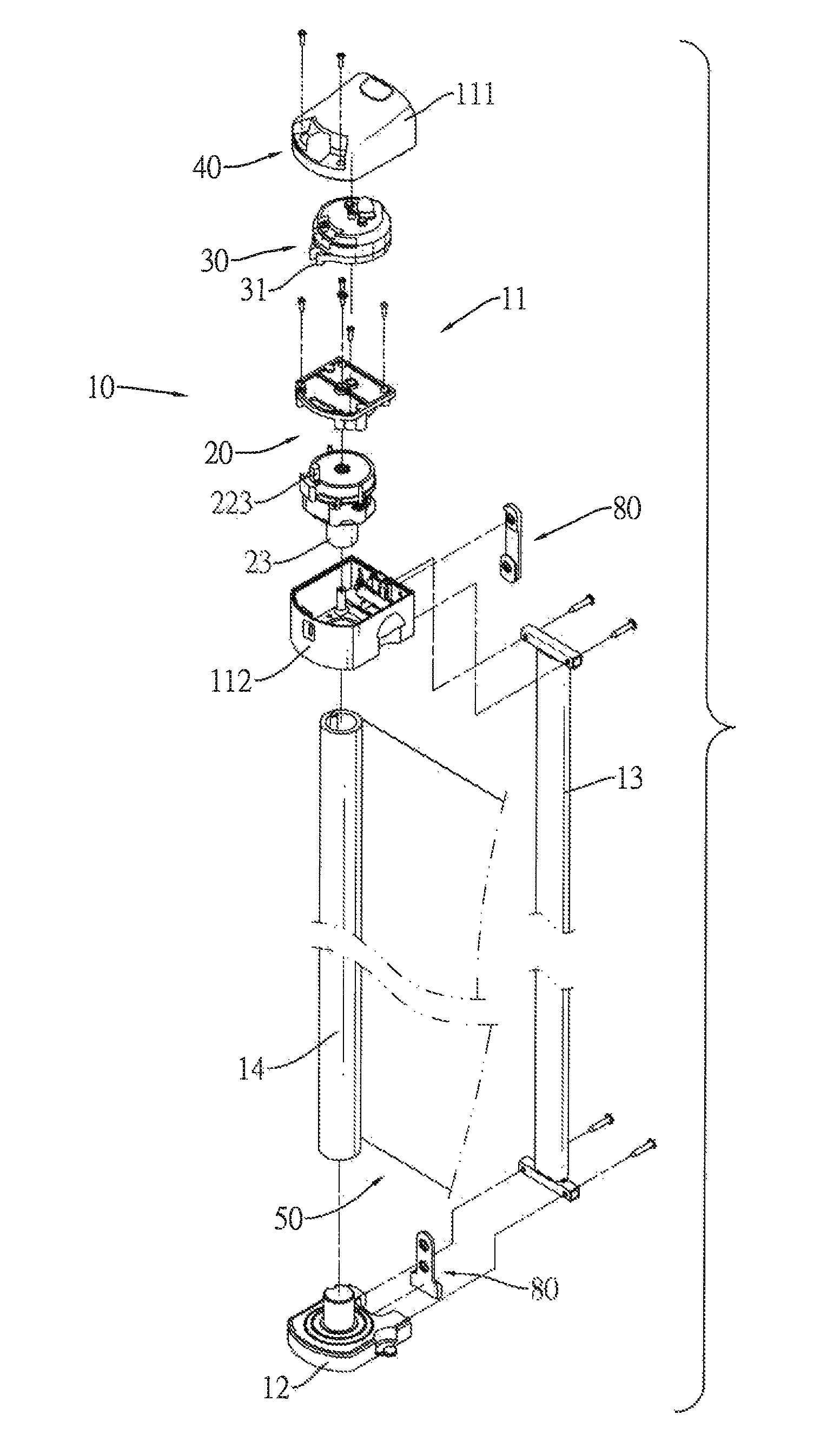
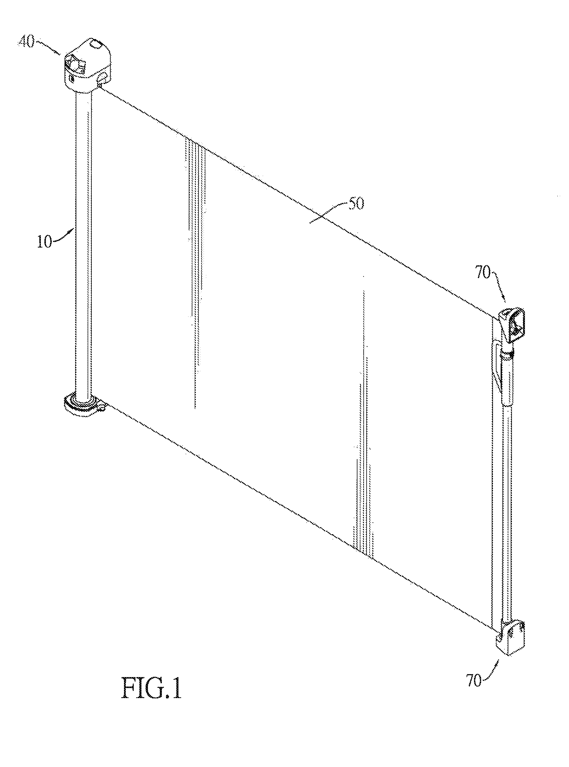
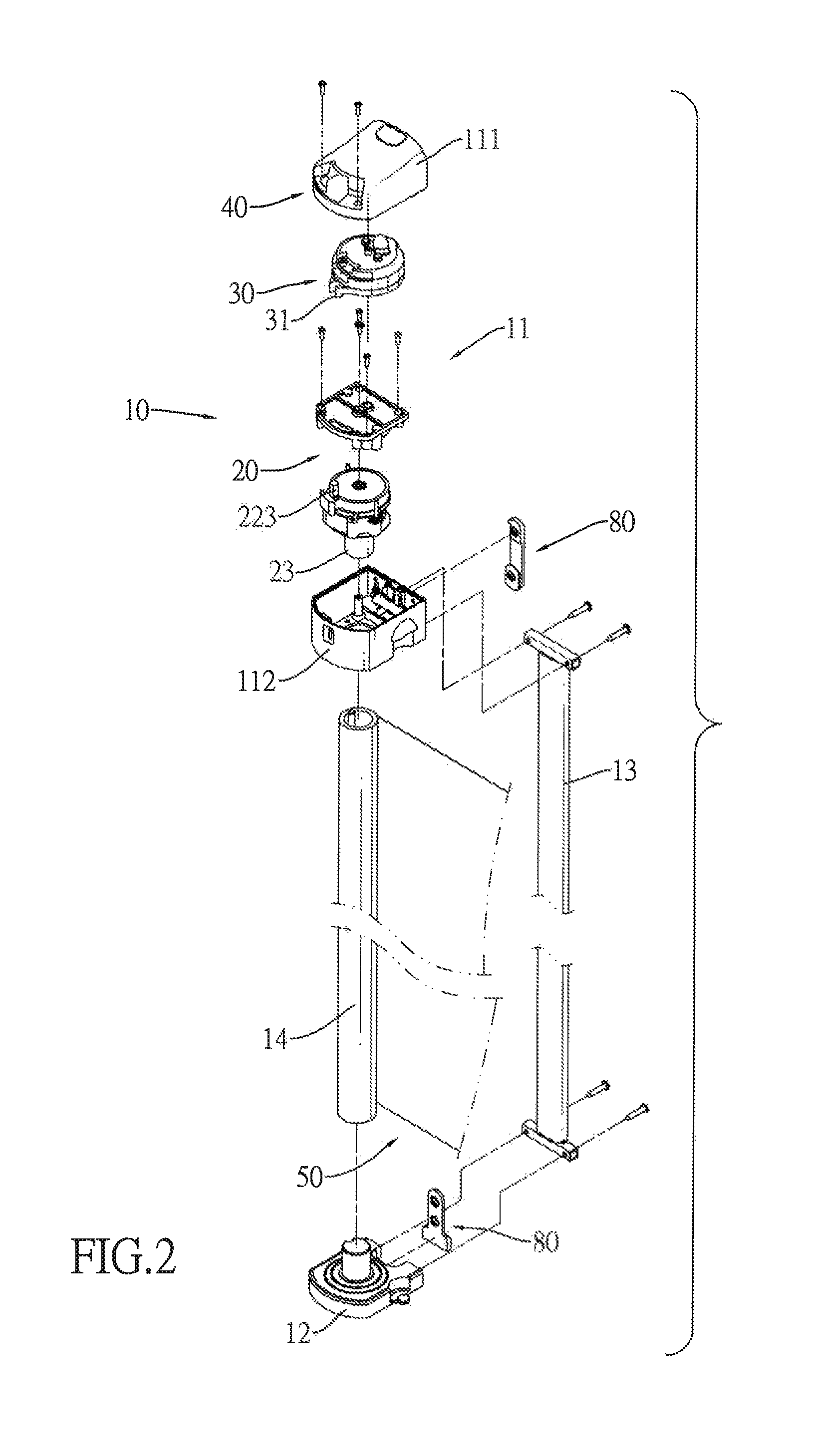
[0032]With reference to FIGS. 1 and 2, a retractable safety gate in accordance with the present invention comprises a mounting assembly 10, a control assembly 20, a delaying assembly 30, an operating assembly 40, a blocking cloth 50, a grip assembly 60, a receiving assembly 70 and a wall assembly 80.

[0033]With reference to FIGS. 2 to 4, the mounting assembly 10 has a top casing 11, a bottom casing 12, a connecting unit 13 and a rotating shaft 14. The top casing 11 has a top cover 111, a top seat 112 and an inner space. The inner space is formed between the top cover 111 and the top seat 112. The bottom casing 12 is disposed below the top casing 11. The connecting unit 13 is connected between the top casing 11 and the bottom casing 12. The rotating shaft 14 is rotatably connected between the top casing 11 and the bottom casing 12.

[0034]With reference to FIGS. 2, 5 and 6, the control assembly 20 is mounted in the top casing 11 and has a control seat 21, a controller 22, a ratchet unit...


PUM


Abstract

A retractable safety gate has a mounting assembly, a control assembly, a delaying assembly, an operating assembly, a blocking cloth, a grip assembly and a receiving assembly. The control assembly has a controller, a ratchet unit and a spiral spring. The spiral spring is connected between the controller and the ratchet unit. Thus, the controller is pulled back to the original position to be closed by the spiral spring, thereby reducing number of the components such that the retractable safety gate has a simplified structure.

Description

CROSS-REFERENCE TO RELATED APPLICATIONS[0001]This application is based upon and claims priority under 35 U.S.C. 119 from China Patent Application No. 201222020287 filed on May 8, 2012, which is hereby specifically incorporated herein by this reference thereto.BACKGROUND OF THE INVENTION[0002]1. Field of the Invention[0003]The present invention relates to a retractable safety gate, especially to a retractable safety gate that is installed at an entrance to household areas that might be unsafe to keep babies or toddlers from entering.[0004]2. Description of the Prior Arts[0005]A retractable safety gate is usually installed indoors to keep babies or toddlers from entering household areas that might be unsafe, such as kitchen, stairs, or bathrooms. The retractable safety gate may also be used to restrict pets within a particular area at home.[0006]A conventional retractable safety gate has a mounting assembly, a receiving assembly and a blocking cloth. The mounting assembly and the rece...

Claims


Application Information

Patent Timeline
Patent Type & Authority Patents(United States)
IPC IPC(8): E06B9/13E06B9/60E06B11/04E06B9/56E06B9/00
CPCE06B9/00E06B9/13E06B2009/002E06B11/04E06B9/60
Inventor WANG, TSUNG-HSIANG
Owner WANG TSUNG HSIANG
Why Eureka
Try Eureka