Illumination sources with thermally-isolated electronics

a technology of electronic components and illumination sources, applied in the field of high-efficiency lighting sources, can solve the problems of slow adoption of alternative lighting sources, many people are still reluctant to switch to these alternative light sources, and the waste of lamps cannot be simply disposed of at the curbside, so as to reduce the cross section, reduce the amount of potting materials, and improve the reliability of components

Active Publication Date: 2014-11-11
KORRUS INC
View PDF131 Cites 19 Cited by
  • Summary
  • Abstract
  • Description
  • Claims
  • Application Information

AI Technical Summary

Benefits of technology

[0012]This invention relates to high efficient lighting sources. More specifically, the invention relates to a LED lighting source and methods of manufacturing thereof. Some general goals include, to increase light output without increasing device cost or device size, to enable coverage of many beam angles, and to provide a high reliability product for long life (ROI).
[0015]The MR16 form factor heat sink facilitates the dissipation of heat. The heat sink includes an inner core that has a diameter less than half the outer diameter of the heat sink. In various embodiments, the inner core is less than one third, one fourth, and one fifth the outer diameter. The silicon substrate of the LEDs is directly bonded to the inner core region via the thermal epoxy.
[0016]In various embodiments, because the diameter of the inner core is much less than the outer diameter, a larger amount of heat dissipating fins can be provided. A number of heat dissipating fin configurations have been developed and studied by the inventors. Typical fin configurations include a number radiating fin “trunks” extending from the inner core. In some embodiments, the number of trunks range from 8 to 35. At the end of each trunk, two or more fin “branches” are provided having “U” branching shape. In various embodiments, at the end of each branch, two or more fin “sub-branches” are provided, also having a “U” branching shape. In various embodiments, the fin thickness of the trunk may be thicker than the branches, which in turn may be thicker than the sub-branches, etc. The amount of heat flow from the inner core towards the outer diameter, airflow, and surface area are therefore engineered to increase heat dissipating capability.
[0019]Other aspects of various embodiments include: simplified construction facilitating high volume manufacturing, flex interconnects to eliminate hand wiring, modular subassembly construction to enable parallel processing. Other features include thermal management aspects: fin branching algorithm, reduced cross section central core, airflow behind lens, single thermal interface, direct die attach, flex printed circuits in base, base contour to minimize potting material, recessed front, ensured airflow with coverage; low-cost manufacturing: flexible printed circuit interconnect (main and interposer), separable driver module, flex circuit light chip interposer, redundant latching and bonding features, and the like. Other aspects include: high temperature operation enabling a densely packed LED array, higher component reliability, high heat dissipation, maximum surface area, maximum airflow, minimum thermal interface losses, minimum length thermal paths within the electronics module, and the like. Advantage with embodiments of the present invention include operating a LED light source reliably at high temperatures, allowing the concentration of a large number of LEDs in a small space while simultaneously operating them at higher power levels.

Problems solved by technology

Despite the availability and improved efficiencies of these other options, many people have still been reluctant to switch to these alternative light sources.
Because the mercury vapor is considered a hazardous material, spent lamps cannot simply be disposed of at the curbside but must be transported to designated hazardous waste disposal sites.
The inventors also believe that another reason for the slow adoption of alternative lighting sources is the low performance compared to the incandescent light bulb.
Further, fluorescent lights typically do not immediately provide light at full brightness, but typically ramp up to full brightness within an amount of time (e.g. 30 seconds).
Further, most fluorescent lights are fragile, are not capable of dimming, have ballast transformers that can emit annoying audible noise, and can fail in a shortened period of time if cycled on and off frequently.
Because of this, fluorescent lights do not have the performance consumers require.
The inventors of the present invention believe, however, that current LED lighting sources themselves have significant drawbacks that cause consumers to be reluctant to using them.
A key drawback with current LED lighting sources is that the light output (e.g. lumens) is relatively low.
Another drawback with current LED lighting sources includes that the upfront cost of the LED is often shockingly high to consumers.
Although the consumer may rationally “make up the difference” over the lifetime of the LED by the LED consuming less power, the inventors believe the significantly higher prices greatly suppress consumer demand.
Because of this, current LED lighting sources do not have the price or performance that consumers expect and demand.
Additional drawbacks with current LED lighting sources includes they have many parts and are labor intensive to produce.
Additional drawbacks with current LED lighting sources, are that the output performance is limited by heat sink volume.
Further, because conventional electronic assembly techniques and LED reliability factors limit PCB board temperatures to about 85 degrees C., the power output of the LEDs is also greatly constrained.
Traditionally, light output from LED lighting sources have been increased by simply increasing the number of LEDs, which has lead to increased device costs, and increased device size.
Additionally, such lights have had limited beam angles and limited outputs.

Method used


Image

  • Illumination sources with thermally-isolated electronics
  • Illumination sources with thermally-isolated electronics
  • Illumination sources with thermally-isolated electronics

Examples


Embodiment Construction

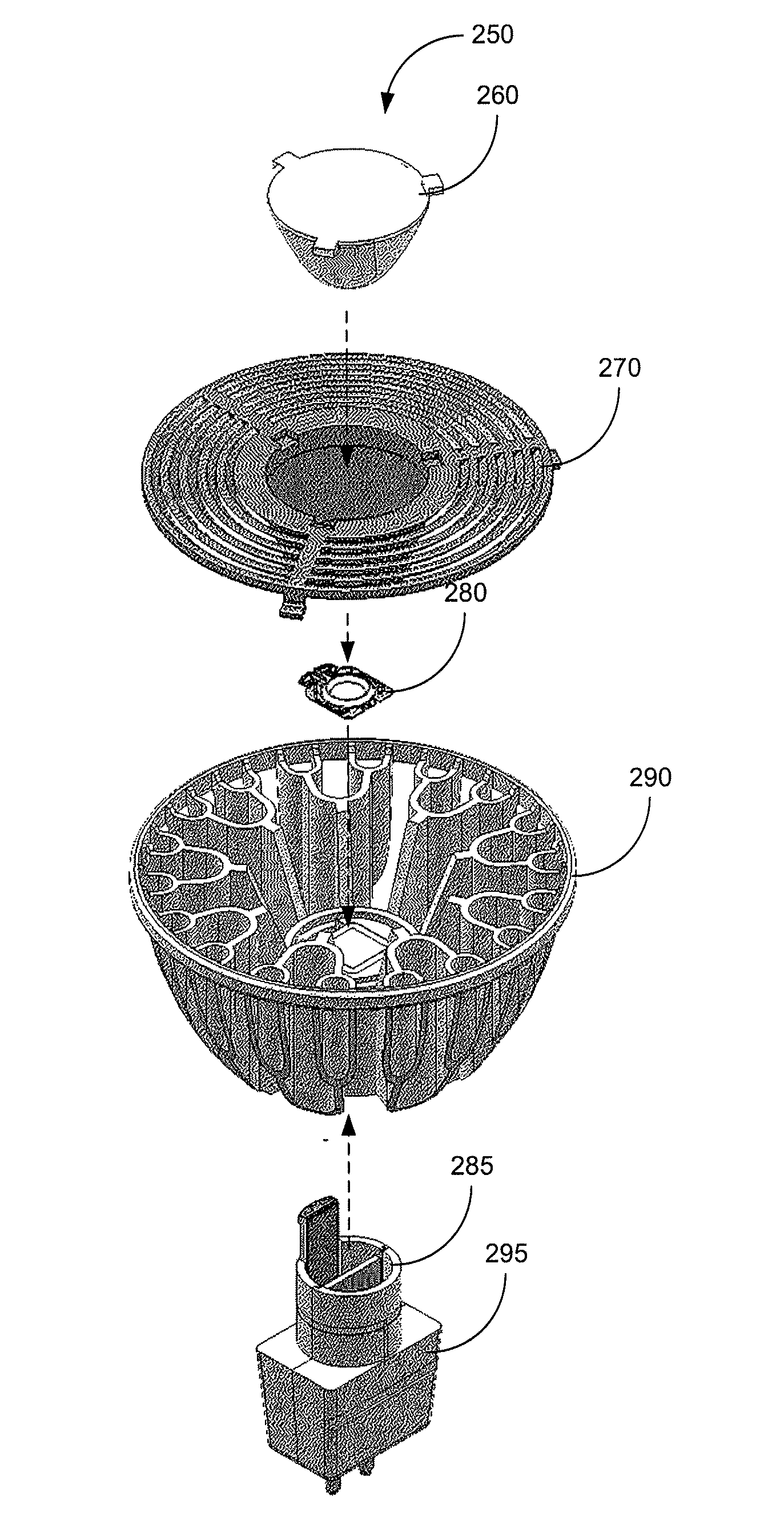
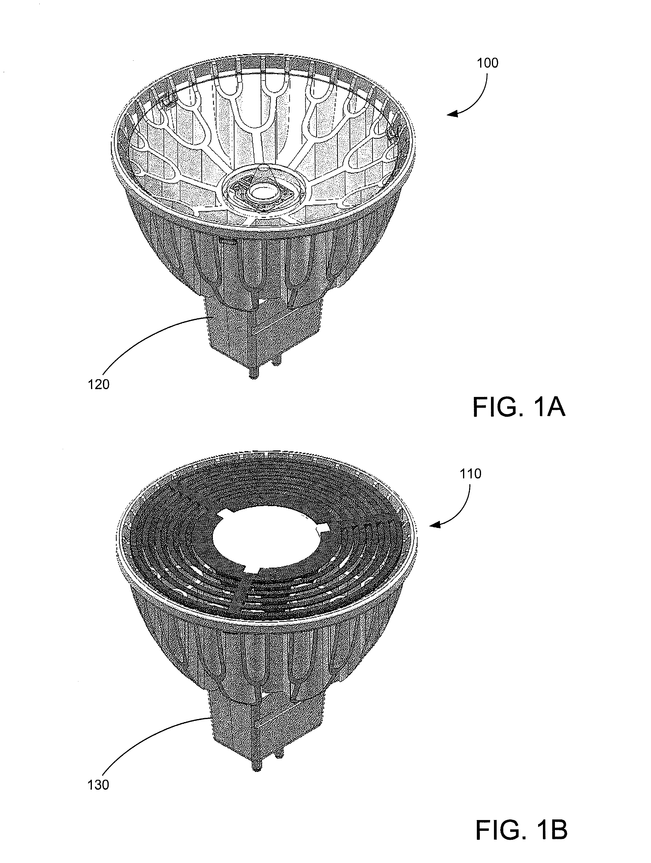
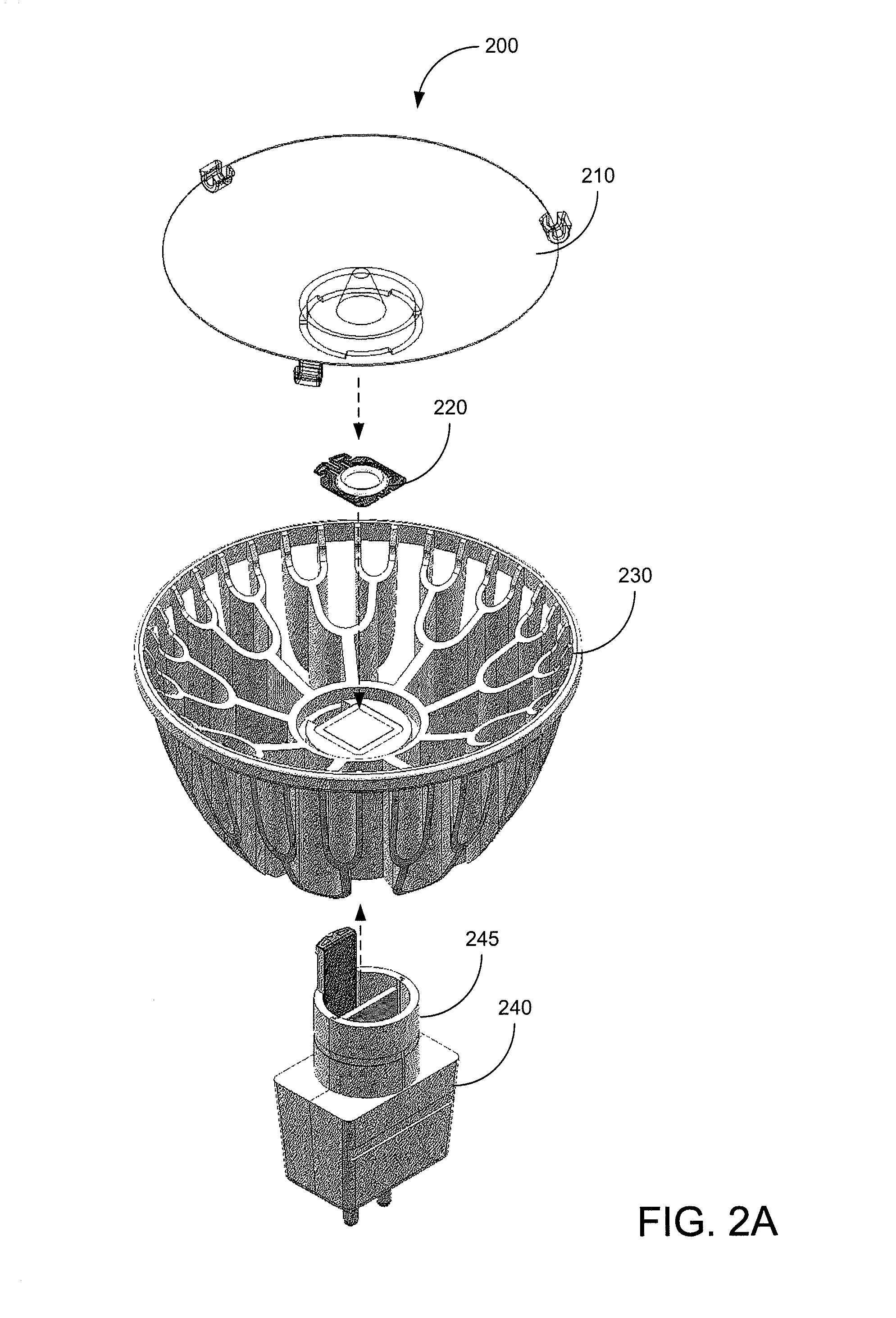
[0030]FIGS. 1A-B illustrate various embodiments of the present invention. More specifically, FIGS. 1A-B illustrate embodiments of MR-16 form factor compatible LED lighting sources 100 and 110 having GU 5.3 form factor compatible bases 120 and 130. Such MR-16 lighting sources typically operate upon 12 volts, alternating current (e.g. VAC). In the examples illustrated, LED lighting source 100 is configured to provide a spot light having a 10 degree beam size and LED lighting source 110 is configured to provide a flood light having a 25 or 40 degree beam size.

[0031]In various embodiments, an LED assembly described in the pending patent applications described above, and variations thereof, may be used within LED lighting sources 100 and 110. Theses LED assemblies are currently under development by the assignee of the present patent application. In various embodiments, LED lighting source 100 may provide a peak output brightness from approximately 7600 to 8600 candelas (with approximatel...


PUM


Abstract

An lighting source includes a driver for outputting electrical power in response to external electrical power, wherein the driver generates heat in response thereto, a lamp coupled to the driver, for outputting light in response to the electrical power, wherein the lamp generates heat in response thereto, a first heat sink physically coupled to the driver for receiving and dissipating heat there from, a second heat sink physically coupled to the light for receiving heat and dissipating heat there from, and an insulating portion disposed between the first heat sink and the second heat sink, wherein the insulating portion is configured to inhibit heat from the lamp from being transferred to the driver.

Description

BACKGROUND OF THE INVENTION[0001]The present invention relates to lighting. More specifically, the present invention relates to high efficiency lighting sources.[0002]The era of the Edison vacuum light bulb will be coming to an end soon. In many countries and in many states, common incandescent bulbs are becoming illegal, and more efficient lighting sources are being mandated. Some of the alternative light sources currently include fluorescent tubes, halogen, and light emitting diodes (LEDs). Despite the availability and improved efficiencies of these other options, many people have still been reluctant to switch to these alternative light sources.[0003]The inventors of the present believe that there are several key reasons why consumers have been slow to adopt the newer technologies. One such reason is the use of toxic substances in the lighting sources. As an example, fluorescent lighting sources typically rely upon mercury in a vapor form to produce light. Because the mercury vap...

Claims


Application Information

Patent Timeline
Patent Type & Authority Patents(United States)
IPC IPC(8): H01K1/62H01J9/24
CPCF21V29/15F21K9/13F21V29/70F21V29/83F21Y2101/02F21K9/90F21V29/74F21K9/23F21Y2105/10F21Y2115/10
Inventor SHUM, FRANK TIN CHUNGSTERANKA, FRANK M.KRAMES, MICHAEL R.
Owner KORRUS INC
Why Eureka
Try Eureka