Light source device, projector, and method of driving discharge lamp

a technology of discharge lamp and light source device, which is applied in the direction of gas discharge lamp usage, climate sustainability, light sources, etc., can solve the problems of reducing the lifetime increasing the distance between the electrodes, and reducing the efficiency of light, so as to suppress the blackening of the discharge lamp, recover from the blackening, and suppress the blackening effect of the discharge lamp

Inactive Publication Date: 2014-11-11
SEIKO EPSON CORP
View PDF22 Cites 3 Cited by
  • Summary
  • Abstract
  • Description
  • Claims
  • Application Information

AI Technical Summary

Benefits of technology

[0012]An advantage of the invention is to provide a light source device, a projector, and a method of driving a discharge lamp while suppressing the blackening of the discharge lamp, and keeping the inter-electrode distance within a allowable distance range.
[0013]An aspect of the invention is directed to a light source device including a discharge lamp having a light emitting case including a hollow section in which a discharge medium is encapsulated, and a pair of electrodes having respective end portions disposed so as to be opposed to each other in the hollow section, a drive device adapted to supply the pair of electrodes with a drive current, a voltage detector adapted to detect an inter-electrode voltage of the pair of electrodes, and a time measurement device adapted to measure time, the drive device is configured to alternately repeat a first alternating current supply interval in which the pair of electrodes are supplied with a first alternating current with a frequency higher than 1 kHz and a second alternating current supply interval in which the pair of electrodes are supplied with a second alternating current with a frequency one of equal to and lower than 1 kHz, a period of the first alternating current supply interval is measured with the time measurement device, the drive device performs a change from the first alternating current supply interval to the second alternating current supply interval when the period of the first alternating current supply interval measured reaches a predetermined period A, a period of the second alternating current supply interval is measured with the time measurement device, and the drive device performs a change from the second alternating current supply interval to the first alternating current supply interval one of when the period of the second alternating current supply interval measured reaches a predetermined period B, and when an absolute value of the inter-electrode voltage of the pair of electrodes reaches a threshold value.
[0014]Thus, it is possible to suppress the blackening of the discharge lamp in the first alternating current supply interval, and further, make the discharge lamp, which is blackened in the second alternating current supply interval, recover from the blackening.
[0015]On the other hand, in the second alternating current supply interval, the projections are provided to the tip portions of the pair of electrodes, and then grow to thereby make it possible to reduce the inter-electrode distance of the pair of electrodes, which has been increased in the first alternating current supply interval.
[0016]By alternately repeating such first alternating current supply interval and second alternating current supply interval, it is possible to drive the discharge lamp while suppressing the blackening of the discharge lamp, and keeping the inter-electrode distance of the pair of electrodes within the allowable distance range.
[0017]Further, in particular, in the initial stage of the lighting of the discharge lamp in which the discharge lamp is difficult to recover from the blackening, it is possible to make the discharge lamp recover from the blackening in the first alternating current supply interval.

Problems solved by technology

However, in this drive method, the arc discharge occurs between a pair of electrodes while the discharge lamp is in the lighting state, and the electrodes are heated to a high temperature, and therefore, the electrodes are melted, and the distance between the electrodes grows.
The growing of the distance between the electrodes during lighting leads to the degradation of the efficiency of the light, which is not preferable.
However, in this drive method, there arises a problem that there occur the blackening, the devitrification, and so on of the discharge lamp main body to thereby reduce the lifetime of the discharge lamp.
However, in the lighting device described in Document 3, since both of the alternating current with the steady lighting frequency and the alternating current with the lower frequency have too low frequencies, there arises a problem that there occur the blackening, the devitrification, and so on of the discharge lamp main body to thereby reduce the lifetime of the discharge lamp.
Further, although the projection is provided to each of the tip portions of the pair of electrodes while the discharge lamp is in the lighting state, the electrodes are gradually consumed while the discharge lamp is lit for a long period of time such as several hundreds or several thousands of hours, and it becomes unachievable to grow the projections to a predetermined size.

Method used


Image

  • Light source device, projector, and method of driving discharge lamp
  • Light source device, projector, and method of driving discharge lamp
  • Light source device, projector, and method of driving discharge lamp

Examples


specific example

[0153]A specific example according to the invention will hereinafter be described.

first specific example

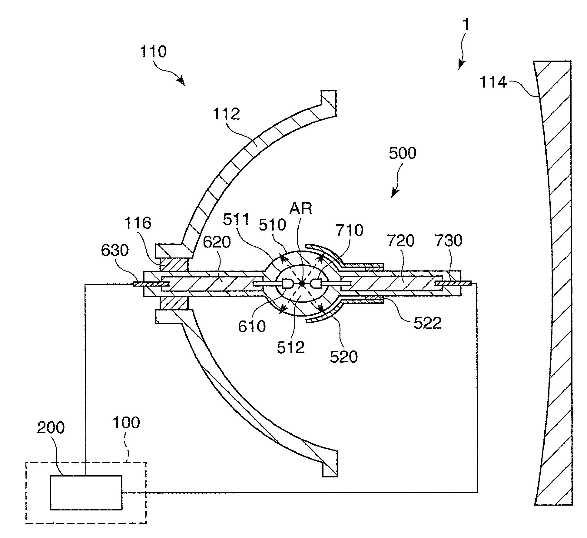
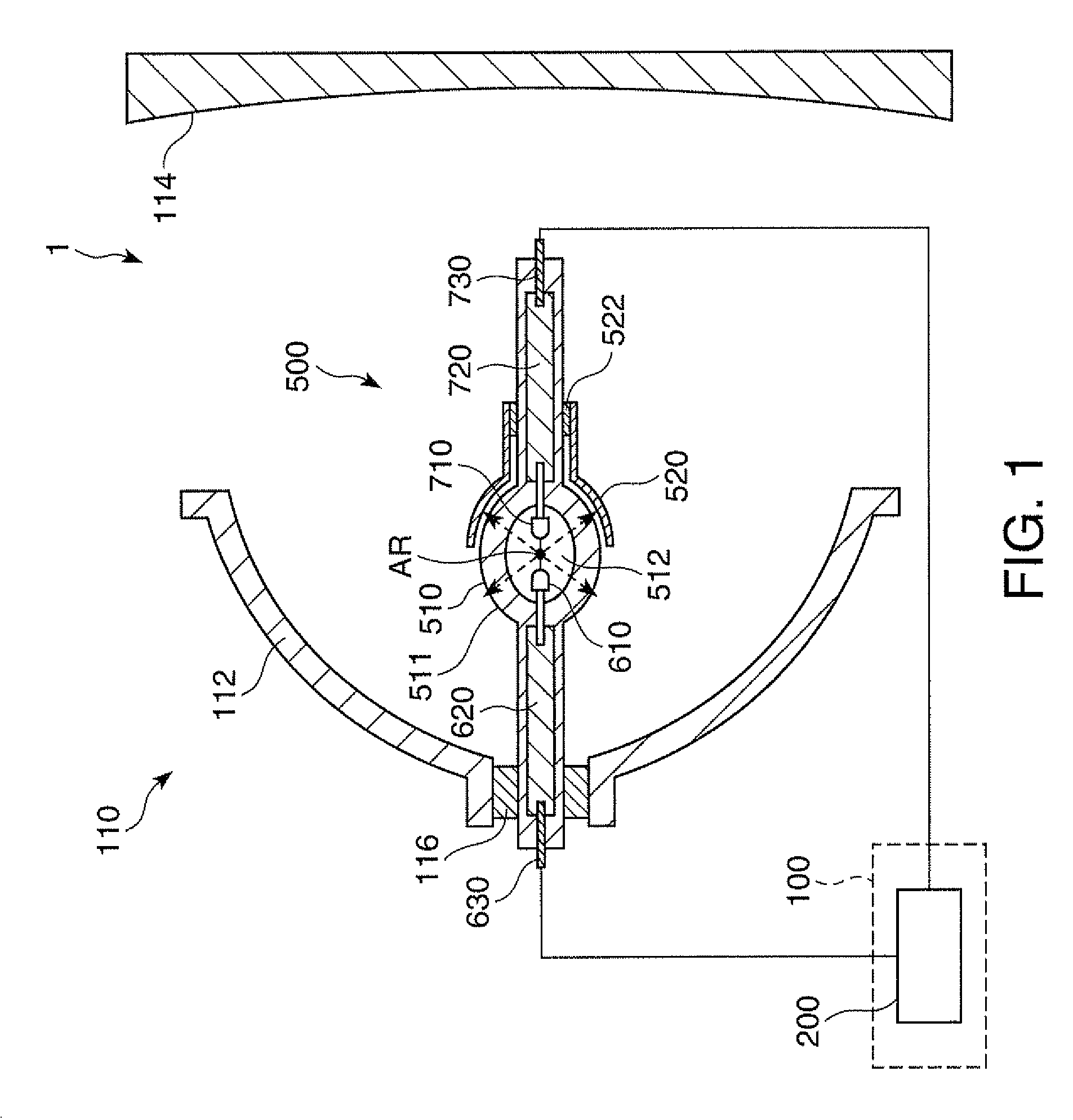
[0154]The light source device shown in FIG. 1 and provided with the configuration described below is manufactured.

[0155]Further, when lighting the discharge lamp, there is performed the control of performing the change from the first alternating current supply interval to the second alternating current supply interval when the period of the first alternating current supply interval reaches the period A, and performing the change from the second alternating current supply interval to the first alternating current supply interval when the period of the second alternating current supply interval reaches the period B or when the absolute value of the inter-electrode voltage of the pair of electrodes reaches the threshold value.

[0156]constituent material of the discharge lamp main body: quartz glass

[0157]encapsulated substances in the discharge lamp main body: argon, mercury, methyl bromide

[0158]air pressure in the discharge lamp main body when lighting: 200 atm

[0159]constituent material...


PUM


Abstract

A light source device includes a discharge lamp having a light emitting case and a pair of electrodes, a drive device, a voltage detector, and a time measurement device, the drive device alternately repeats a first alternating current supply interval and a second alternating current supply interval, measures a period of the first and the second alternating current supply interval with the time measurement device, performs a change from the first alternating current supply interval to the second alternating current supply interval when the period of the first alternating current supply interval reaches a predetermined period A, and performs a change from the second alternating current supply interval to the first alternating current supply interval when the period of the second alternating current supply interval reaches a predetermined period B, or when an absolute value of an inter-electrode voltage of the pair of electrodes reaches a threshold value.

Description

BACKGROUND[0001]1. Technical Field[0002]The present invention relates to a light source device, a projector, and a method of driving a discharge lamp.[0003]2. Related Art[0004]As a light source of a projector, there is used a discharge lamp such as a high-pressure mercury lamp or a metal halide lamp.[0005]Such a discharge lamp is driven with a drive method of, for example, supplying a high-frequency alternating current as a drive current (see, e.g., JP-A-2007-115534 (Document 1)). According to this drive method, stability of discharge can be obtained, blackening and devitrification of the discharge lamp main body can be prevented, and the degradation of the lifetime of the discharge lamp can be suppressed.[0006]However, in this drive method, the arc discharge occurs between a pair of electrodes while the discharge lamp is in the lighting state, and the electrodes are heated to a high temperature, and therefore, the electrodes are melted, and the distance between the electrodes grows...

Claims


Application Information

Patent Timeline
Patent Type & Authority Patents(United States)
IPC IPC(8): H05B41/24H05B41/36H05B41/288H05B37/00H05B39/00H05B41/28H05B41/16H05B41/292
CPCH05B41/2928H05B41/36H05B41/28Y02B20/202H05B41/2887Y02B20/00
Inventor SUZUKI, JUNICHI
Owner SEIKO EPSON CORP
Why Eureka
Try Eureka