Apparatus and method for driving touch sensor

a technology of touch sensor and drive system, which is applied in the direction of instruments, data processing power supply, computing, etc., can solve the problems of limited limited power consumption reduction of conventional touch controller, and increase in touch calculation time and power consumption. , to achieve the effect of reducing touch calculation time and power consumption and reducing power consumption

Active Publication Date: 2014-11-11
LG DISPLAY CO LTD
View PDF20 Cites 39 Cited by
  • Summary
  • Abstract
  • Description
  • Claims
  • Application Information

AI Technical Summary

Benefits of technology

[0013]An object of the present invention is to provide an apparatus and method for driving a touch sensor in which a group sensing method per region or a local channel sensing method in a selected region is used depending upon whether touch is made, thereby reducing touch calculation time and power consumption.
[0014]Another object of the present invention is to provide an apparatus and method for driving a touch sensor in which per-region group sensing is used in a power save mode, thereby reducing power consumption.

Problems solved by technology

As a result, reduction of touch calculation time and power consumption is limited due to unnecessary touch calculation time.
As the size of the touch sensor increases, touch calculation time and power consumption also increase.
For this reason, reduction of power consumption of the conventional touch controller is limited.

Method used


Image

  • Apparatus and method for driving touch sensor
  • Apparatus and method for driving touch sensor
  • Apparatus and method for driving touch sensor

Examples


Embodiment Construction

[0047]Reference will now be made in detail to the preferred embodiments of the present invention, examples of which are illustrated in the accompanying drawings. Wherever possible, the same reference numbers will be used throughout the drawings to refer to the same or like parts.

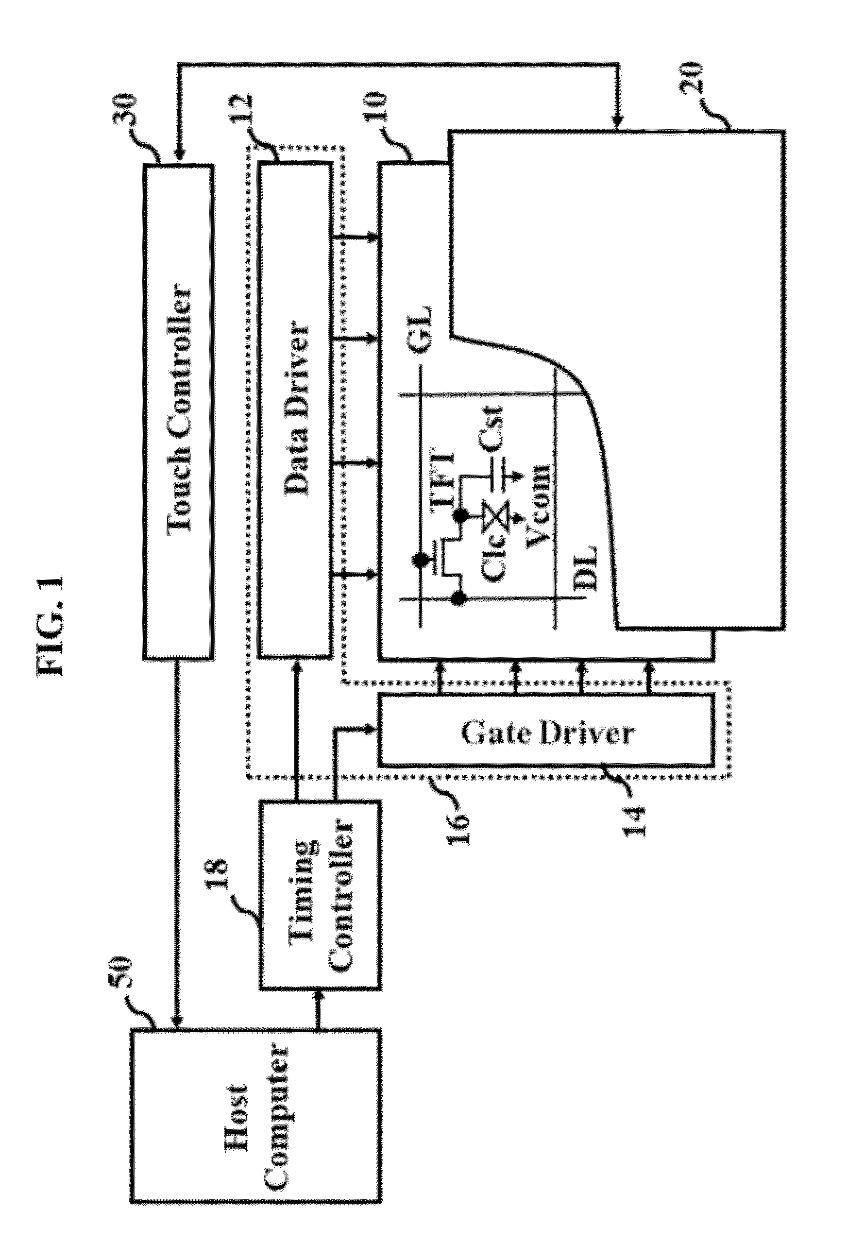
[0048]FIG. 1 is a block diagram showing the construction of a display device including a touch sensor drive apparatus according to an embodiment of the present invention.

[0049]Referring to FIG. 1, the display device includes a display panel 10, a panel drive unit 16 including a data driver 12 and gate driver 14 to drive the display panel 10, a timing controller 18 to control the panel drive unit 16, a touch sensor 20 disposed on the display panel 10, and a touch controller 30 to drive the touch sensor 20. The timing controller 18 and the touch controller 30 are connected to a host computer 50.

[0050]The timing controller 18 and the data driver 12 may be individually integrated into integrated circuits (ICs), ...


PUM


Abstract

Disclosed is an apparatus and method for driving a touch sensor in which a group sensing method per region or a local channel sensing method in a selected region is used depending upon whether touch is made, thereby reducing touch calculation time and power consumption. An apparatus for driving a touch sensor, including a plurality of first conduction lines and a plurality of second conduction lines, includes a touch controller to divide the touch sensor into a plurality of regions, to periodically sense whether touch has been made per region using a group sensing mode, to select a touch region when the touch region is detected, and to sense whether touch has been made per channel using a channel sensing mode only in the selected region.

Description

[0001]This application claims the benefit of Korean Patent Applications No. 10-2010-0140249 and No. 10-2010-0140250, filed on Dec. 31, 2010, which are hereby incorporated by reference as if fully set forth herein.BACKGROUND OF THE INVENTION[0002]1. Field of the Invention[0003]The present invention relates to a touch sensor drive system, and more particularly, to an apparatus and method for driving a touch sensor that is capable of reducing touch calculation time and power consumption.[0004]2. Discussion of the Related Art[0005]In recent years, a touch sensor (touchscreen, touch panel) enabling information to be input on screens of various display devices by touch has been widely used as an information input device of a computer system. Users can move and select displayed information simply by touching a screen using a finger or stylus, and therefore, people of all ages and both sexes can easily use such a touch sensor.[0006]The touch sensor senses a position at which touch is genera...

Claims


Application Information

Patent Timeline
Patent Type & Authority Patents(United States)
IPC IPC(8): G06F3/044G06F3/045G06F1/32G06F3/041
CPCG06F3/0416G06F3/044G06F1/3262G06F3/041661G06F3/041662G06F3/0446
Inventor SEO, SEONG-MO
Owner LG DISPLAY CO LTD
Why Eureka
Try Eureka