
Dynamically reconfigurable graphics layer system and method

a graphics layer and dynamic reconfiguration technology, applied in the field of graphical user interfaces, can solve problems such as inability to provide processing and memory resources, inefficient or poorly designed transitions, and unsatisfactory interfaces

Active Publication Date: 2014-11-11
APPLE INC
View PDF61 Cites 2 Cited by
  • Summary
  • Abstract
  • Description
  • Claims
  • Application Information

AI Technical Summary

Benefits of technology

This approach enhances the user interface's responsiveness and efficiency by leveraging hardware capabilities for transitions while conserving resources, ensuring a smooth and pleasing user experience without compromising device performance.

Problems solved by technology

A transition that is too jarring or abrupt may result in an unpleasant interface.
Alternatively, a transition that is inefficient or poorly designed may be interpreted by the user as a slow or unresponsive user interface.
However, as the demand for smaller portable electronic devices with a wide range of functionality increases, processing and memory resources may not be available and may constrain the ability of a device to provide these special effects.

Method used


Image

  • Dynamically reconfigurable graphics layer system and method
  • Dynamically reconfigurable graphics layer system and method
  • Dynamically reconfigurable graphics layer system and method

Examples


Embodiment Construction

[0024]One or more specific embodiments of the present invention will be described below. These described embodiments are only exemplary of the present invention. Additionally, in an effort to provide a concise description of these exemplary embodiments, all features of an actual implementation may not be described in the specification. It should be appreciated that in the development of any such actual implementation, as in any engineering or design project, numerous implementation-specific decisions must be made to achieve the developers' specific goals, such as compliance with system-related and business-related constraints, which may vary from one implementation to another. Moreover, it should be appreciated that such a development effort might be complex and time consuming, but would nevertheless be a routine undertaking of design, fabrication, and manufacture for those of ordinary skill having the benefit of this disclosure.

[0025]Turning now to the figures, FIG. 1 depicts an el...


PUM


Abstract

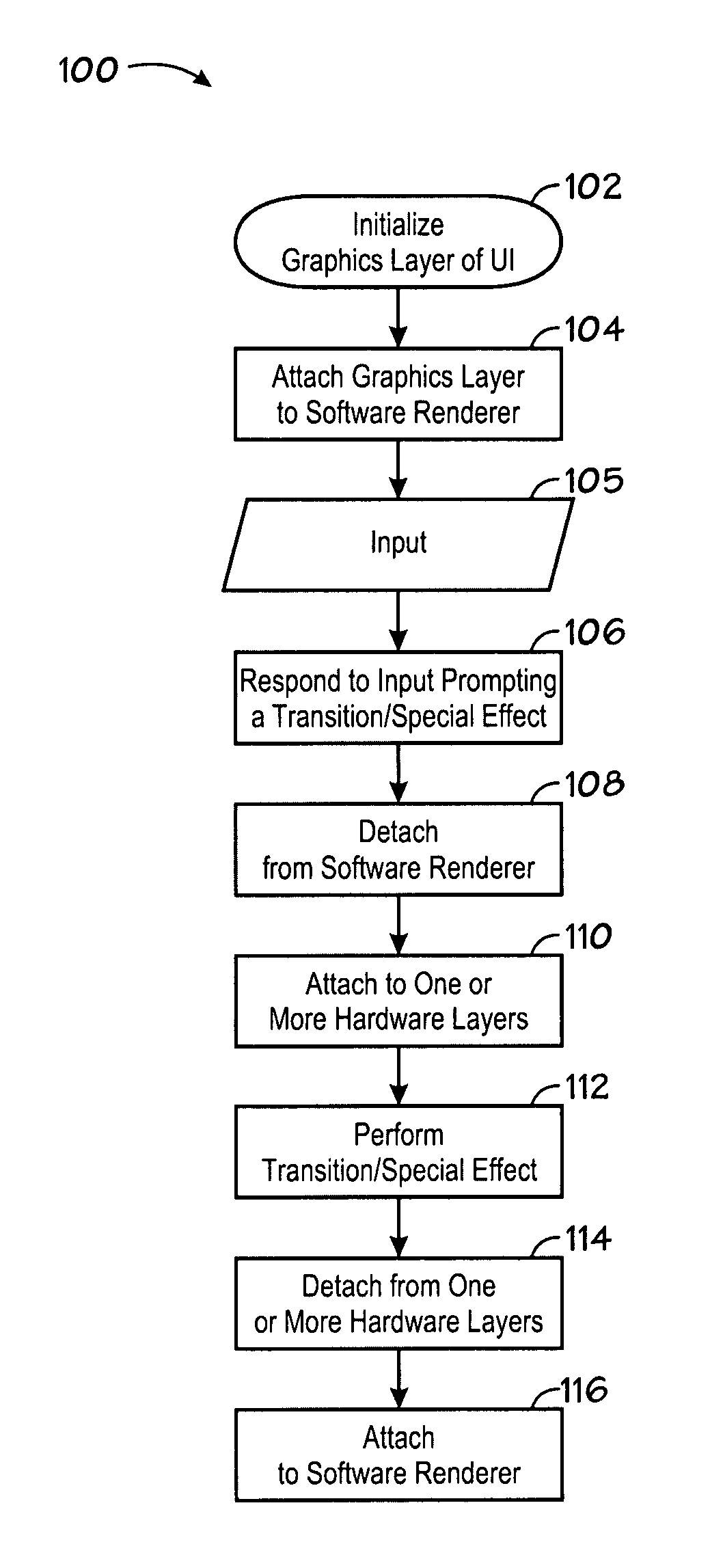
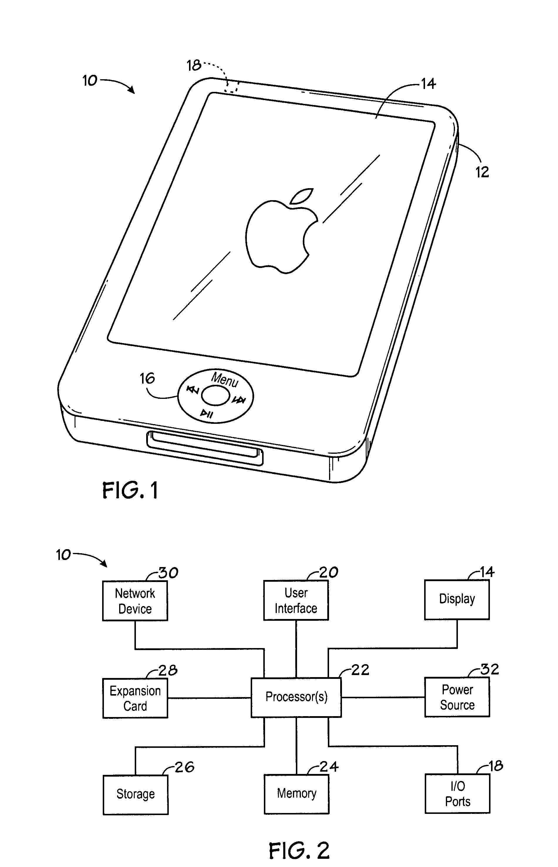
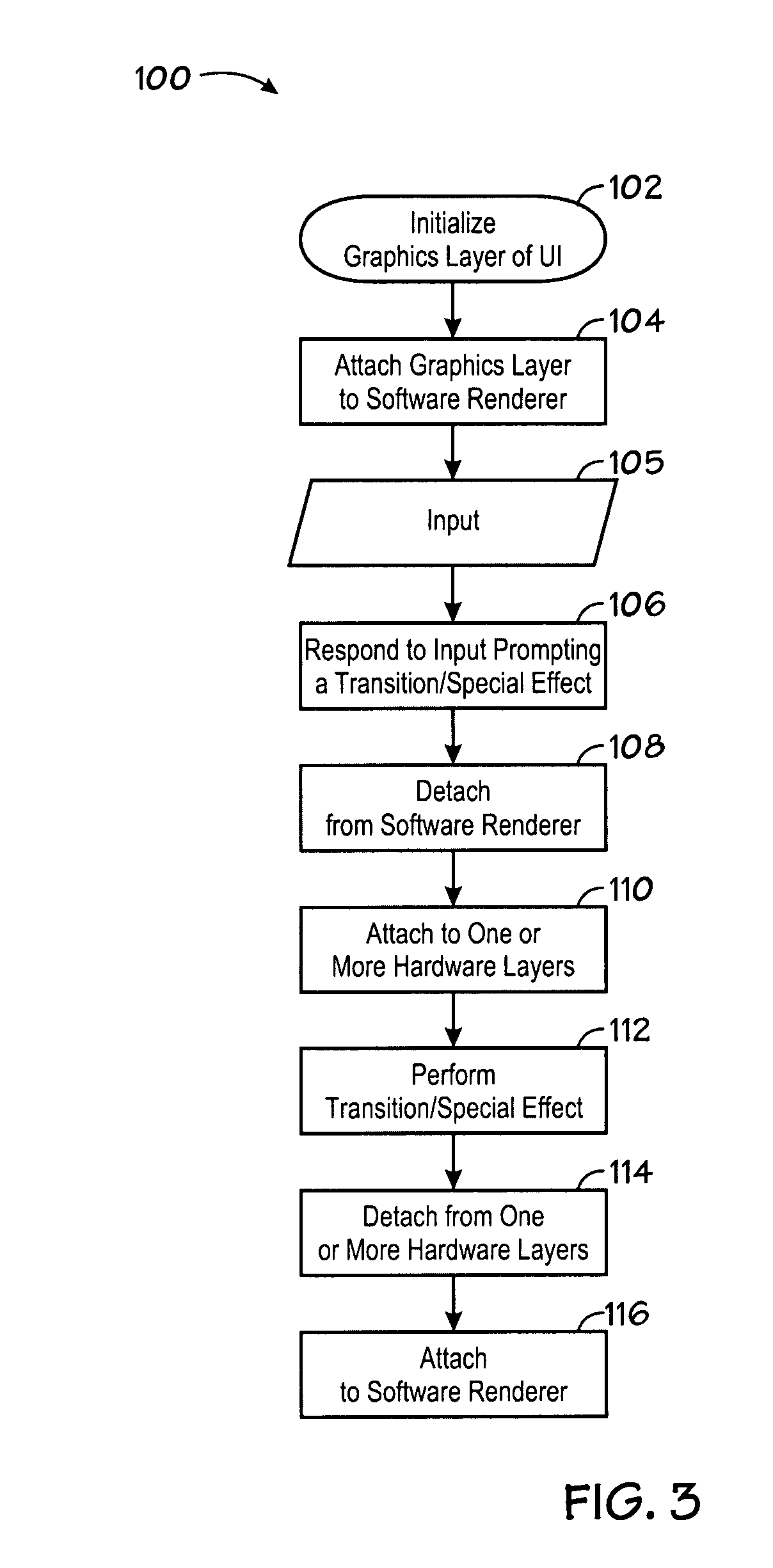
A method of displaying a user interface in a portable electronic device is provided. The method includes displaying a user interface via a graphics layer attached to a software renderer, detaching the graphics layer from the software renderer, and attaching the graphics layer to one or more of a plurality of hardware layers, such that the display of the graphics layer is facilitated by one or more features of at least one of the hardware layers. An electronic device is provided that includes a display, a processor coupled to the display and configured to provide a plurality of hardware layers, and a user interface comprising a graphics layer, wherein the display of the graphics layer is facilitated by one or more features of at least one of the hardware layers, wherein the graphics layer dynamically attaches to or detaches from one or more of the plurality of hardware layers.

Description

BACKGROUND OF THE INVENTION[0001]1. Field of the Invention[0002]The present invention relates generally to graphical user interfaces and more particularly to a graphical user interface for a portable electronic device.[0003]2. Description of the Related Art[0004]This section is intended to introduce the reader to various aspects of art that may be related to various aspects of the present invention, which are described and / or claimed below. This discussion is believed to be helpful in providing the reader with background information to facilitate a better understanding of the various aspects of the present invention. Accordingly, it should be understood that these statements are to be read in this light, and not as admissions of prior art.[0005]The graphical user interface (“GUI”) of an electronic device may accomplish a variety of tasks and present a variety of information to a user. The user sees and interacts with the GUI, so it is beneficial if the GUI presents information and c...

Claims


Application Information

Patent Timeline
Patent Type & Authority Patents(United States)
IPC IPC(8): G09G5/00G06F9/44
CPCG06F9/4443G06F9/451
Inventor BOETTCHER, JESSE W.HUANG, SZU-WENAVKAROGULLARI, GOKHAN
Owner APPLE INC
Learn More