Image forming system including a first image forming apparatus for controlling a second image forming apparatus to shift into a sleep mode
a technology of image forming system and image forming apparatus, which is applied in the direction of digital output to print units, instruments, digitally marking record carriers, etc., can solve the problem of insufficient power consumption
- Summary
- Abstract
- Description
- Claims
- Application Information
AI Technical Summary
Benefits of technology
Problems solved by technology
Method used
Image

Examples
first embodiment
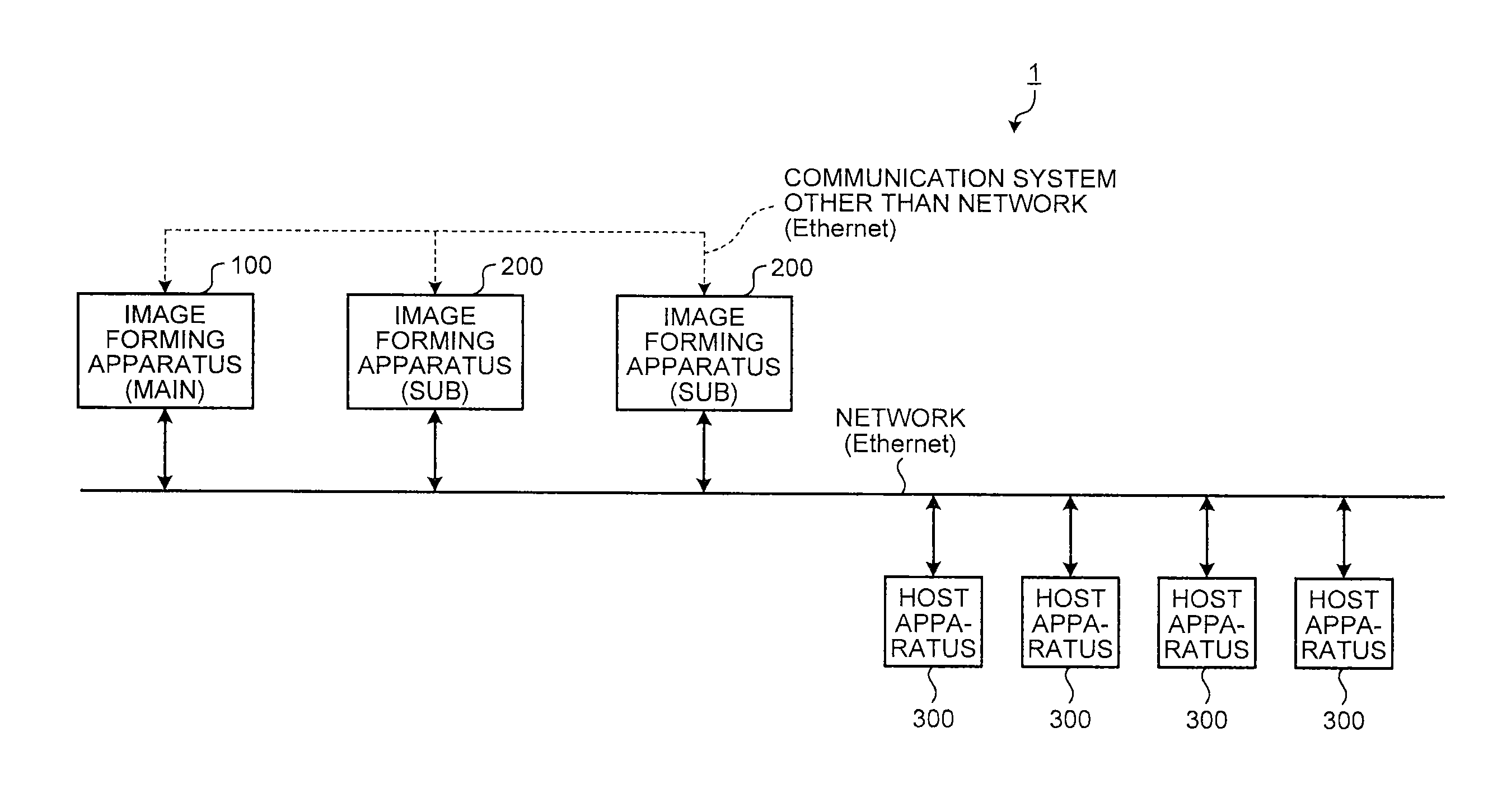
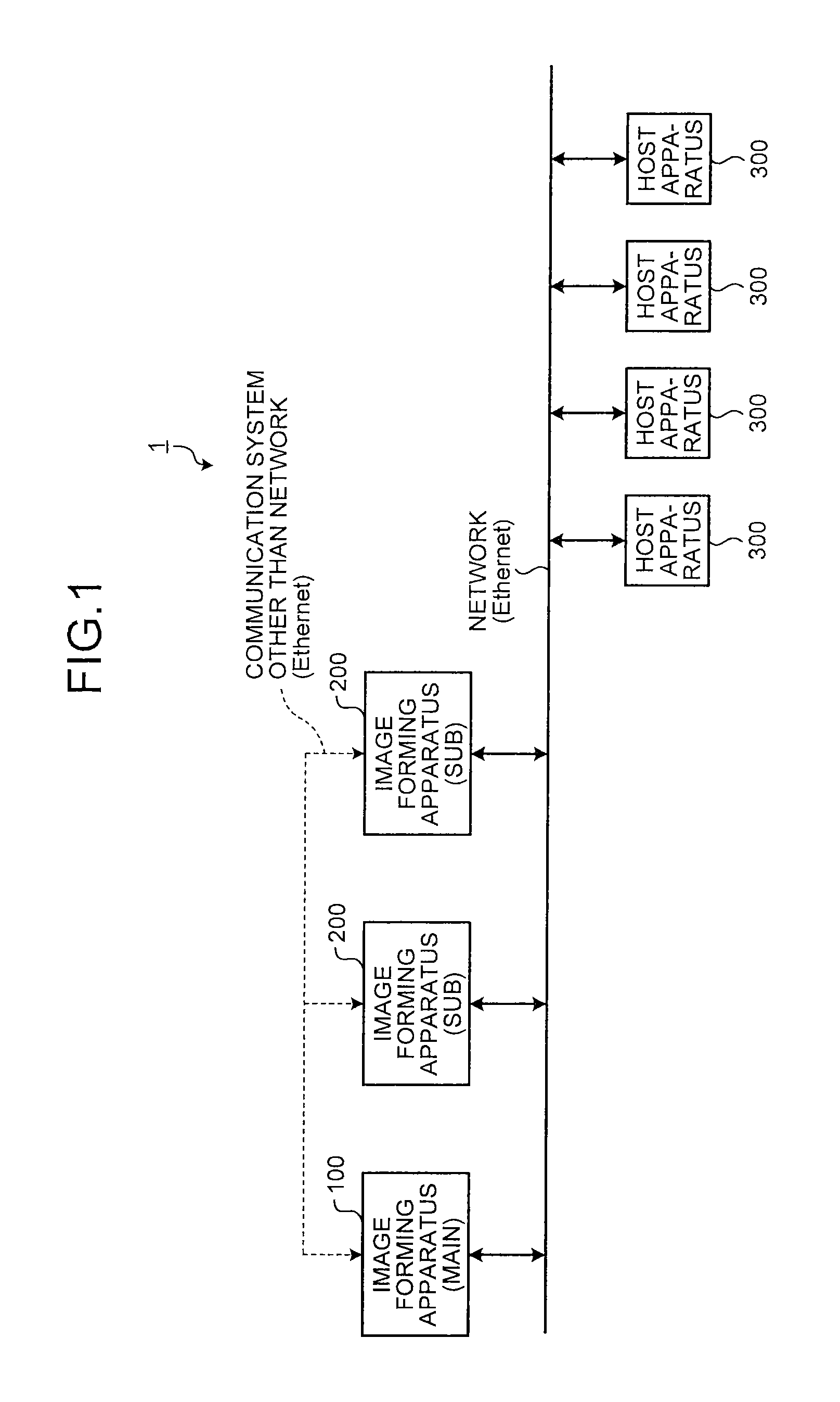
[0022]FIG. 1 is a drawing illustrating a schematic configuration example of an image forming system 1 in a first embodiment. As illustrated in FIG. 1, the image forming system 1 includes a main image forming apparatus 100, sub image forming apparatuses 200, and host apparatuses 300 that are capable of being connected to each other through a network (Ethernet (registered trademark)). Although two sub image forming apparatuses 200 are included in the image forming system 1 and four host apparatuses 300 are included therein in the example of FIG. 1, their numbers are not limited to this example. Any number of sub image forming apparatuses 200 and host apparatuses 300 can be included in the image forming system 1 (it is sufficient that they are equal to or more than one). It is sufficient that the image forming system 1 includes the main image forming apparatus 100 and the sub image forming apparatus 200 that are capable of being connected to each other. For example, a part excluding th...
second embodiment
[0075]The following describes a second embodiment. The second embodiment is different from the above-mentioned first embodiment in a point that each of the image forming apparatuses (the first image forming apparatus 100 and the second image forming apparatuses 200) further includes a power generation unit 400 and a power accumulation unit 500 as illustrated in FIG. 9. Although FIG. 9 illustrates the configuration of the first image forming apparatus 100, the configurations of the second image forming apparatuses 200 are the same as that of the first image forming apparatus 100.
[0076]The power generation unit 400 is a device that generates electric power. The power generation unit 400 can be configured by a device that generates electric power from natural energy, such as a solar cell and a thermoelectric conversion element. The power accumulation unit 500 is a device that accumulates the electric power generated by the power generation unit 400. Although the power accumulation unit...
third embodiment
[0079]The following describes a third embodiment. Hardware configurations of image forming apparatuses (the first image forming apparatus 100 and the second image forming apparatuses 200) according to the third embodiment are the same as those in the second embodiment and explanation of portions common to those in the above-mentioned embodiments is omitted appropriately. FIG. 10 is a block diagram illustrating an example of functions of the first image forming apparatus 100 in the third embodiment. As illustrated in FIG. 10, the first image forming apparatus 100 further includes a power accumulation amount monitoring unit 185 and a threshold setting unit 190. Although the respective functions of the power accumulation amount monitoring unit 185 and the threshold setting unit 190 are executed when the microcomputer 115 executes the programs stored in the ROM and the like in this example, the embodiment is not limited thereto. For example, at least one function of the power accumulati...
PUM
 Abstract
Description
Claims
Application Information
PatSnap Eureka turns technology decisions into work you can execute. Powered by our Innovation Knowledge Graph, it runs expert workflows across engineering, life sciences, materials and intellectual property. Get your review-ready output in minutes.


