Micro-electrode array package using liquid crystal polymer and manufacturing method thereof

a technology of liquid crystal polymer and micro-electrode, which is applied in the direction of prosthesis, semiconductor/solid-state device details, therapy, etc., can solve the problems of poor processability of lcps, limited application of micro-electrodes, etc., and achieve high-density multi-channel systems, not time-efficient, and reduce time

Active Publication Date: 2014-11-11
SEOUL NAT UNIV R&DB FOUND +1
View PDF21 Cites 29 Cited by
  • Summary
  • Abstract
  • Description
  • Claims
  • Application Information

AI Technical Summary

Benefits of technology

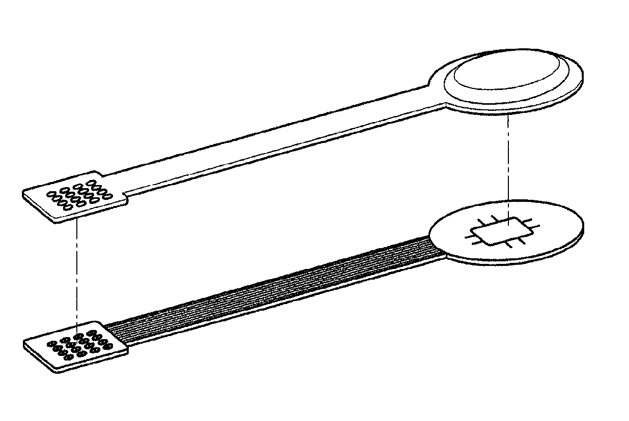
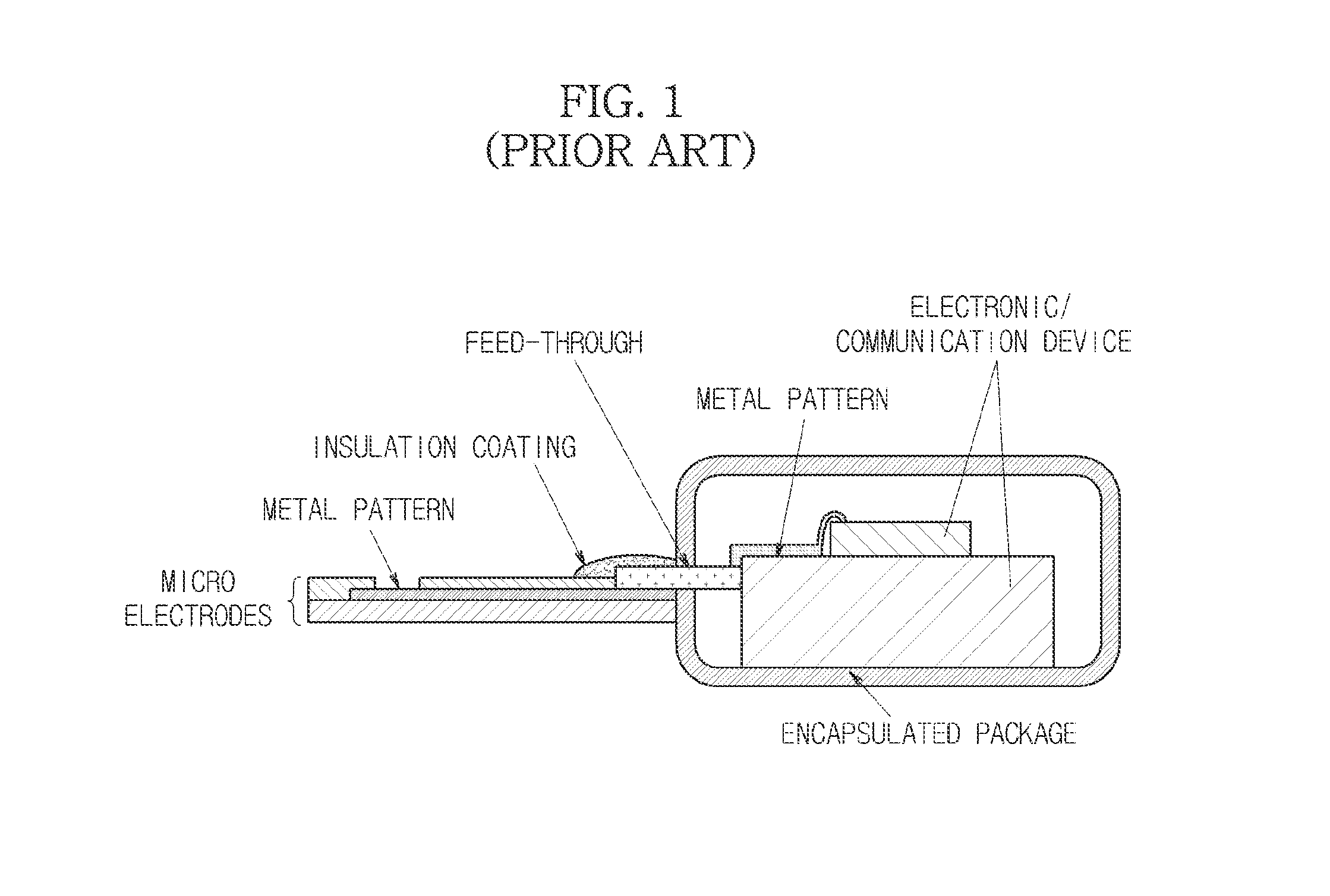
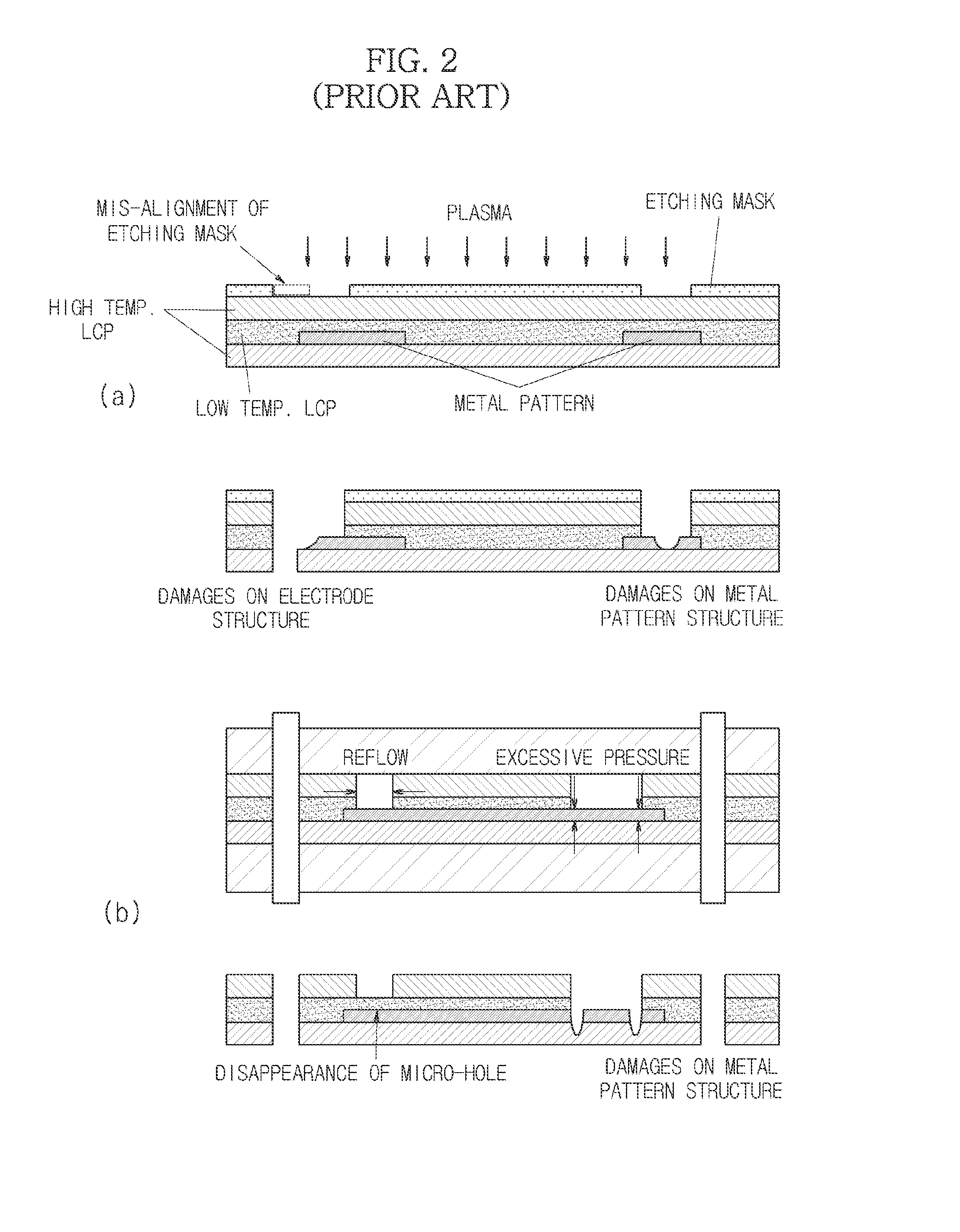
[0008]The method disclosed herein enables manufacture of a micro-electrode array package in a stable and prompt manner. On the contrary, the processes of the related art have disadvantages in that they include long-term plasma etching operations, thereby causing damages on electrode patterns formed of metals, and are not time-efficient. In addition, the method disclosed herein avoids a need for forming an etching mask pattern and plasma etching operation, and thus reduces the time required for manufacturing micro-electrode array packages. Further, the method disclosed herein uses a single material for encapsulating micro-electrodes and other sections so that the assembled sections are not exposed to the exterior, and thus may be advantageous to achieve high-density multi-channel systems.

Problems solved by technology

Conventional micro-electrodes using polymers such as polyimide and parylene are susceptible to the in vivo environment, and thus are limited in their applications.
However, because such LCPs have poor processability, there is an imminent need for a novel method.

Method used


Image

  • Micro-electrode array package using liquid crystal polymer and manufacturing method thereof
  • Micro-electrode array package using liquid crystal polymer and manufacturing method thereof
  • Micro-electrode array package using liquid crystal polymer and manufacturing method thereof

Examples


Embodiment Construction

[0017]Exemplary embodiments now will be described more fully hereinafter with reference to the accompanying drawings, in which exemplary embodiments are shown. This disclosure may, however, be embodied in many different forms and should not be construed as limited to the exemplary embodiments set forth therein. Rather, these exemplary embodiments are provided so that this disclosure will be thorough and complete, and will fully convey the scope of this disclosure to those skilled in the art. In the description, details of well-known features and techniques may be omitted to avoid unnecessarily obscuring the presented embodiments.

[0018]The terminology used herein is for the purpose of describing particular embodiments only and is not intended to be limiting of this disclosure. As used herein, the singular forms “a”, “an” and “the” are intended to include the plural forms as well, unless the context clearly indicates otherwise. Furthermore, the use of the terms a, an, etc. does not de...


PUM

PropertyMeasurementUnit
melting temperatureaaaaaaaaaa
surface morphologyaaaaaaaaaa
pressuresaaaaaaaaaa

Abstract

Disclosed herein is a micro-electrode array package including a micro-electrode array comprising: a substrate section including a liquid crystal polymer; an electrode section collecting and transferring bio-signals; and a cover section insulating and protecting the electrode section and including a liquid crystal polymer, wherein the electrode section is disposed in contact with one surface of the substrate section, the cover section is adhered in contact with the surface of the substrate section on which the electrode section is disposed, and a space independent from the external environment is formed between the substrate section and the cover section adhered thereto. Disclosed herein too is a method for manufacturing a micro-electrode array package, including: forming alignment holes in a substrate section including a liquid crystal polymer and a cover section including a liquid crystal polymer; forming site window holes for an electrode section-exposure in the cover section; forming an electrode section on one surface of the substrate section; aligning the substrate section and the cover section by the alignment holes, and adhering the substrate section and the cover section with each other; and cutting the substrate section and the cover section adhered thereto to provide an outer shape.

Description

TECHNICAL FIELD[0001]This disclosure relates to a micro-electrode array package using a liquid crystal polymer and a method for manufacturing the same. More particularly, this disclosure relates to a micro-electrode array package that allows electrodes and signal processing and communication modules required for realizing sensors and neural prosthetics to be used for a long time while not being affected by moisture and ions in vivo, and to a method for manufacturing the same.BACKGROUND ART[0002]In general, the term ‘micro-electrode array’ refers to a structure attached to or implanted into a living body to convert bio-chemical responses and bio-signals into electric signals to be collected, or to deliver electric signals for neural stimulation.[0003]The technology of micro-electrode array package disclosed herein includes bio-signal recording and stimulating electrodes (also referred to as ‘micro-electrodes’ hereinafter) and encapsulated packages thereof. Particularly, since the bio...

Claims


Application Information

Patent Timeline
Patent Type & Authority Patents(United States)
IPC IPC(8): A61B5/04A61N1/05H01L23/48H01L23/66H01L23/498H01L21/56A61B5/00H01L23/31A61B5/296
CPCH01L23/3135A61B5/04001H01L2924/00A61B2562/0209H01L23/49894A61B2562/125H01L23/48A61B2562/046H01L21/56H01L23/66H01L2223/6677H01L2924/0002A61B5/6877Y10T29/49117Y10T29/49155A61B5/24H01L29/00A61F2/02
Inventor KIM, SUNG JUNELEE, SEUNG WOOLEE, CHOONG JAEAN, SOONKWAN
Owner SEOUL NAT UNIV R&DB FOUND
Why Eureka
Try Eureka