Retractable, low-profile storm shield systems and methods

a low-profile, storm shield technology, applied in the direction of sliding/moving grilles, door/window protection devices, curtain suspension devices, etc., can solve the problem of limited protection and achieve the effect of increasing protection and reducing volum

Inactive Publication Date: 2014-11-18
STORM SOLUTIONS
View PDF12 Cites 12 Cited by
  • Summary
  • Abstract
  • Description
  • Claims
  • Application Information

AI Technical Summary

Benefits of technology

[0012]Embodiments of the present invention relate generally to storm protection systems and more specifically to a flexible, retractable storm protection system with reduced volume and increased protection. The system can comprise a screen made of a strong flexible material, or a composite of such materials. The screen material can comprise, for example and not limitation, a PVC coated aramid fabric (e.g., Kevlar®), Mylar®, vinyl, nylon, polyester, polypropylene, or fiberglass, or combinations thereof. The screen can comprise a loop sewn, welded, or both into both vertical edges and / or both horizontal edges.
[0013]The present system can further comprise vertical channels for securing the vertical edges of the screen. The vertical channels can be substantially C-shaped with a hem rod located inside the channel. In some embodiments, the vertical channels can have multiple pieces to facilitate assembly and installation. The loops in the vertical sides of the screen can encircle the hem rod such that the screen is both guided inside the channel, when being deployed or retracted, and retained in the channel when the screen encounters wind pressure or other forces. The hem rod acts to locate and secure the screen in substantially the same manner as a conventional hem cord, while significantly reducing storage requirements for the screen when retracted.
[0014]In some embodiments, the system can be installed on the outside of a building penetration, such as for example and not limitation, a door or a window. In this configuration, the system can also protect the door or window from solar heat gain, insect or pest infiltration, and thermal loss, in addition to storm and water damage. In some embodiments, the system can be installed on the inside of a building penetration. In this configuration, the system can provide the same protections for the building, and, for example, limited protection for the door or window. In some embodiments, the system can provide a light control layer to reduce or eliminate light infiltration into the building (e.g., the system can act as a “black-out” shade).
[0016]The system can further comprise a horizontal support unit. The horizontal support unit can span all, or substantially all, of the free horizontal edge of the screen (i.e., the end of the screen not attached to the take-up roll). In some embodiments, such as when the top-down configuration is used, the horizontal support unit can be weighted and can facilitate the deployment of the screen. In other embodiments, such as when the bottom-up configuration is installed, the horizontal support unit can comprise a lightweight, rigid material. In some embodiments, the horizontal support unit can be attached to the screen using one or more horizontal loops in the screen. In other embodiments, the horizontal support unit can further comprise, for example and not limitation, latches, catches, or pins for securing the screen in the deployed, or partially deployed, position. In some embodiments, the horizontal support unit can further comprise a guide, molded or attached to the horizontal support unit, and sized and shaped to travel in the slot in the vertical channels.

Problems solved by technology

In this configuration, the system can provide the same protections for the building, and, for example, limited protection for the door or window.

Method used


Image

  • Retractable, low-profile storm shield systems and methods
  • Retractable, low-profile storm shield systems and methods
  • Retractable, low-profile storm shield systems and methods

Examples


Embodiment Construction

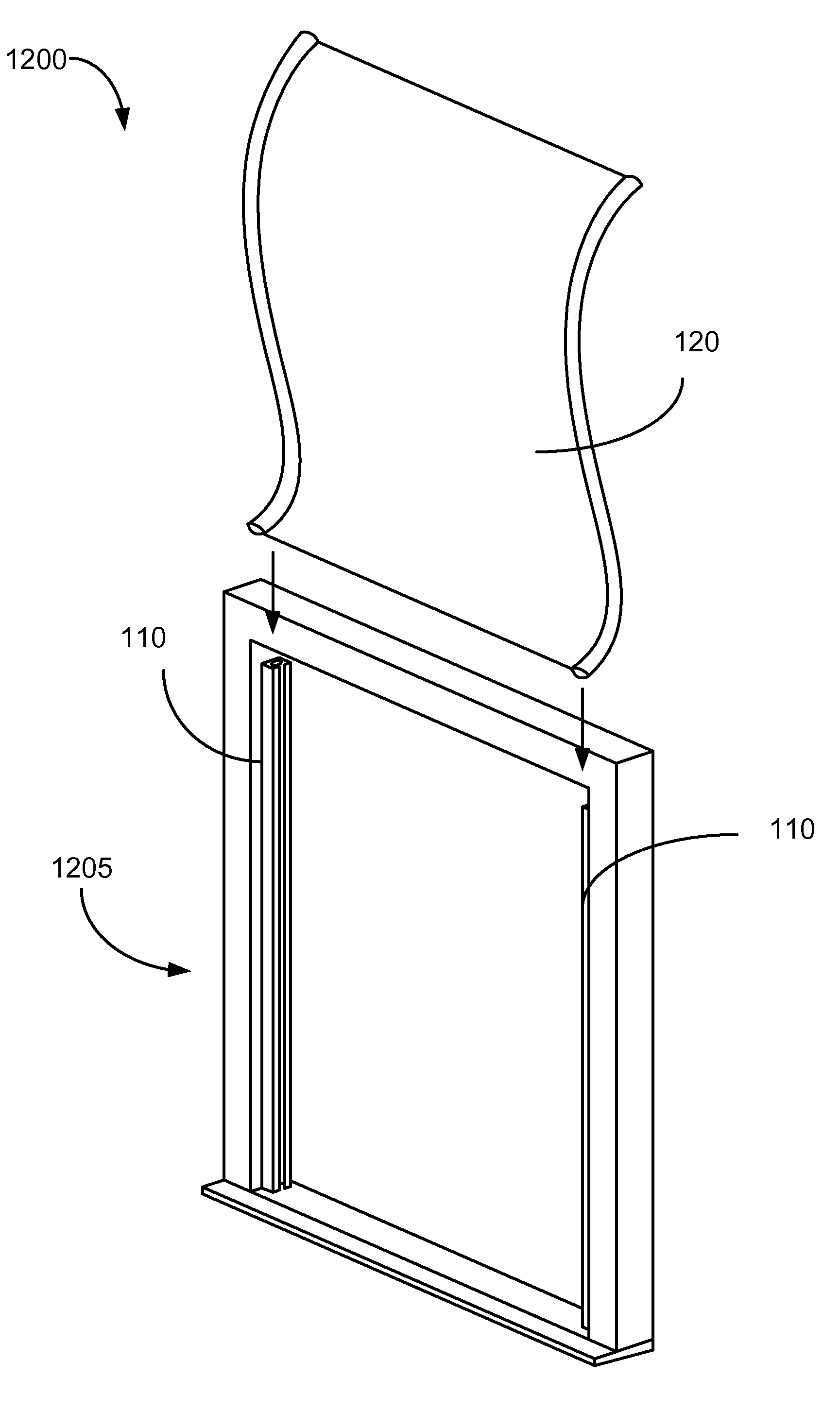
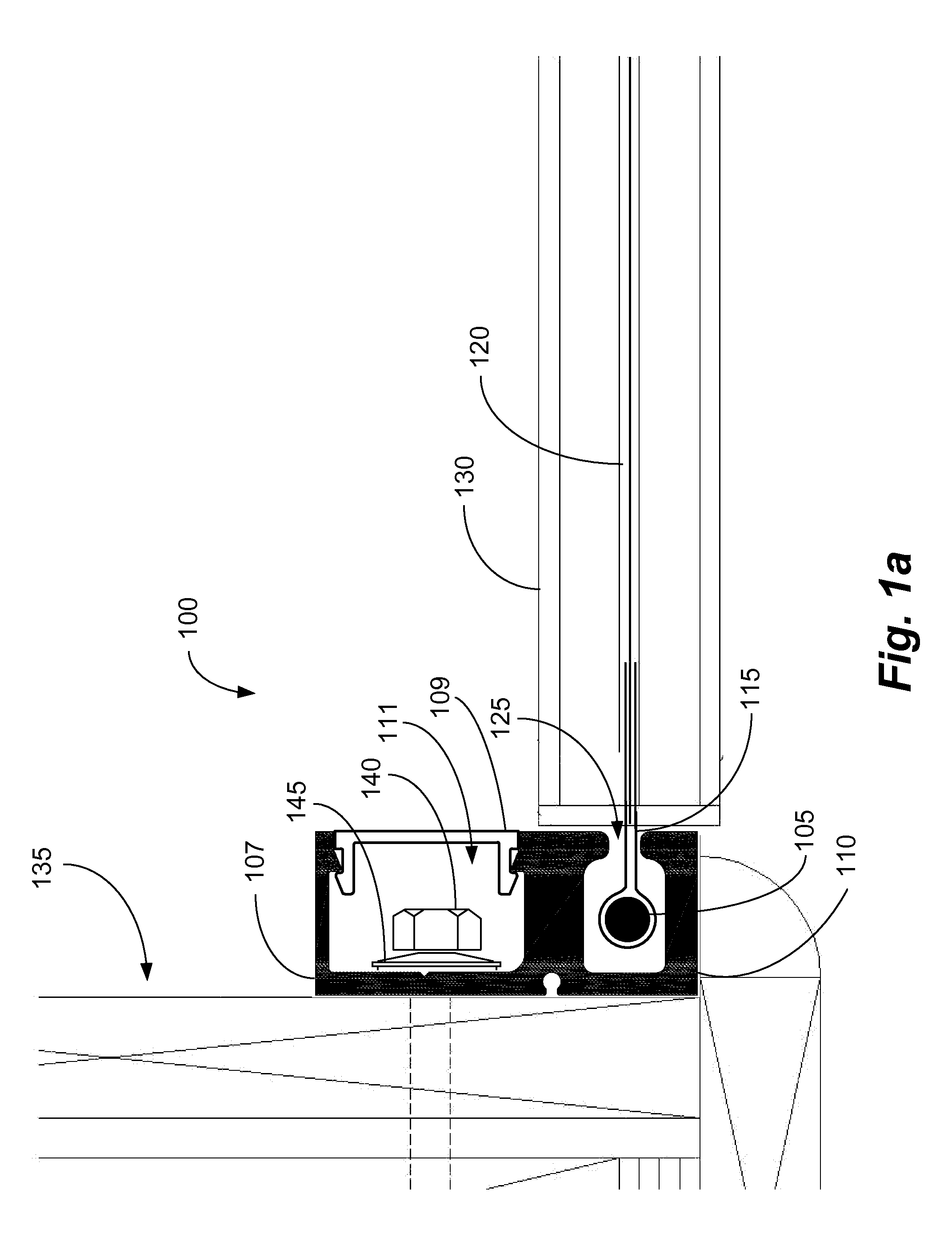
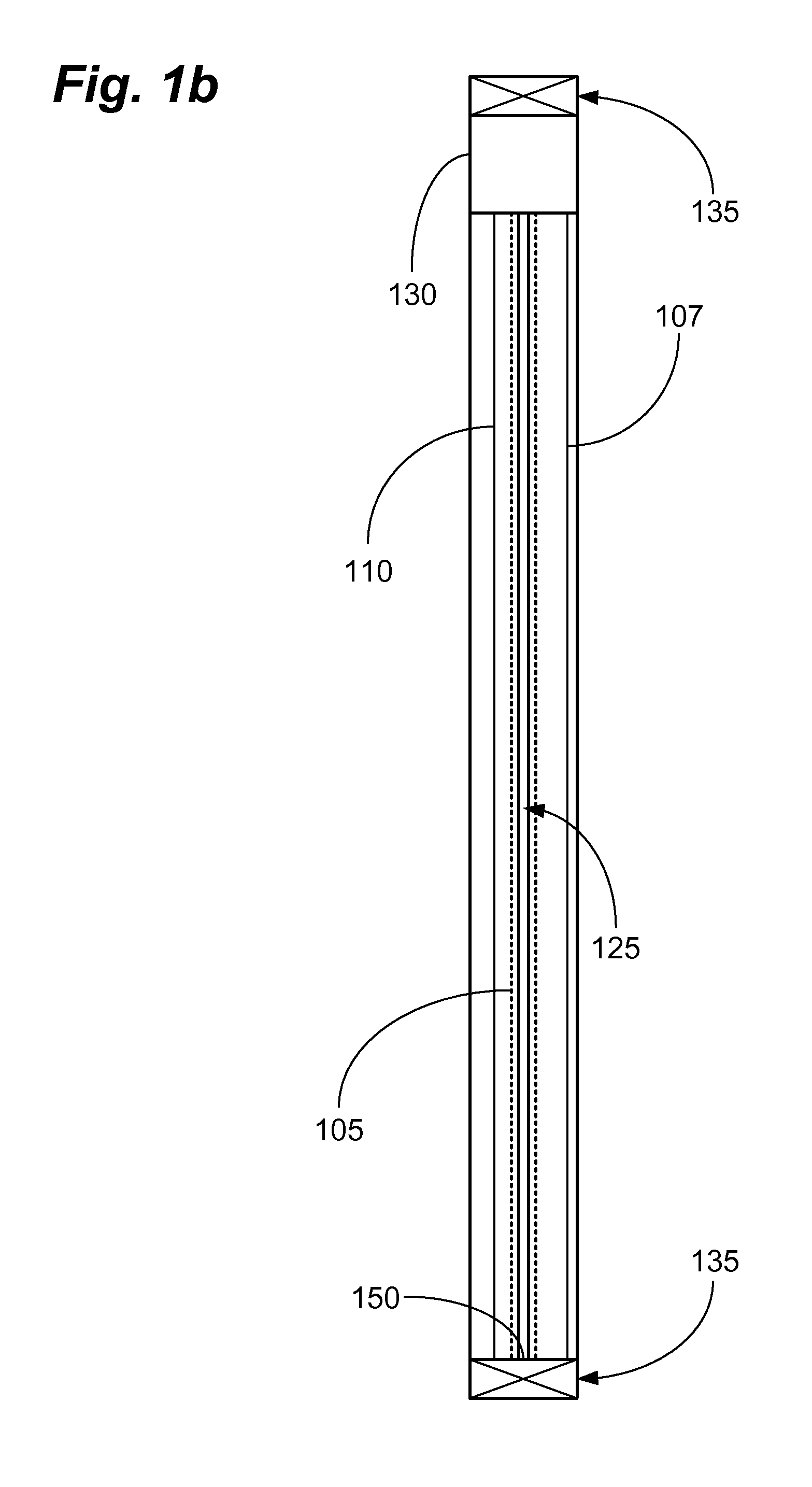
[0046]Embodiments of the present invention relate generally to storm protection systems and more specifically to a flexible, retractable storm protection system with a reduced storage volume and increased protection than have been conventionally provided. The system replaces a conventional hem cord design with a stationary hem rod located in a retention channel to provide the security of the hem cord system with the compact size of a hem-only system. The system can employ a retention channel with a hem rod disposed therein. The screen can have a loop sewn, welded, or otherwise manufactured into each vertical edge sized to easily slip over the hem rod. The hem rod can retain the screen in the retention track even when exposed to, for example, high wind, driving rain, and / or impacts from flying objects.

[0047]To simplify and clarify explanation, the system is described below as a system for protecting the windows and doors of residential and commercial buildings. One skilled in the art...


PUM


Abstract

A self-contained system for protecting building penetrations is disclosed. The system can include a housing containing a take-up roll and a screen made from a flexible, strong fabric-like material suitable for resisting high winds, driving rain, and wind-driven missiles. The system can further comprise a deflector or roller to maintain the angle of deployment of the screen. The system can further include a weight bar attached to the end of the screen to assist in deploying the screen. The system can further comprise a dual pulley system to assist in deploying the screen and to hold the screen in the deployed position. The system can include wipers to clean the screen as it is retracted into the enclosure. The system can further comprise an integrated or separate light control, or “black-out” screen. The system enclosures can comprise various hinged covers to facilitate service, repair, and storage.

Description

CROSS REFERENCE TO RELATED APPLICATIONS[0001]This Application claims benefit under 35 U.S.C. §120 and is a continuation-in-part of U.S. patent application Ser. No. 12 / 882,331 filed 15 Sep. 2010, which claims benefit under 35 USC §119(e) of U.S. Provisional Patent Application Ser. No. 61 / 346,490 filed 20 May 2010 and U.S. Provisional Patent Application Ser. No. 61 / 242,466 filed 15 Sep. 2009. Each of the above-listed applications is herein incorporated by reference as if fully set forth below in their entireties.BACKGROUND OF THE INVENTION[0002]1. Field of the Invention[0003]The present invention relates to a retractable system for protecting penetrations in buildings, and particularly to a retractable, flexible, low-profile, solar, insect, thermal, and storm (“SITS”) protection system for windows and doors. The present invention enables a storage and deployment mechanism for roll-up storm protection screens that is approximately 50-60% smaller than conventional systems while containi...

Claims


Application Information

Patent Timeline
Patent Type & Authority Patents(United States)
IPC IPC(8): E06B9/13E06B9/58E06B9/56A47H1/00E06B9/06A47G5/02E06B9/00
CPCE06B9/13E06B9/581E06B5/003E06B9/00E06B2009/005E06B9/0692
Inventor TREMAINE, III, BURTON G.RIVERA, VICTOR
Owner STORM SOLUTIONS
Why Eureka
Try Eureka