Deployment assembly and introducer

Active Publication Date: 2014-11-18
COOK MEDICAL TECH LLC
View PDF8 Cites 35 Cited by
  • Summary
  • Abstract
  • Description
  • Claims
  • Application Information

AI Technical Summary

Benefits of technology

[0009]The feature of the actuator being able to provide at least a part of its restoring force in a direction other than the direction of retraction of the retractable element can provide a smaller and in some instances substantially no force component in the withdrawal direction of the introducer. As a result of this, there can be significantly less jolting of the introducer in the longitudinal direction thereof and thus less risk of the distal end of the introducer being moved unintentionally out of position. This problem can manifest itself with systems which may provide a large force in the withdrawal direction.
[0012]The advantage of the above features is that when the spring is released so as to retract the sprung element to thereby withdraw the sheath, the force produced by the spring is less likely and in most instances unlikely to cause the introducer to jolt in the retraction direction.
[0015]According to another aspect of the present invention, there is provided a deployment assembly for deploying one or more components of an endovascular introducer assembly provided with a retractable element, the deployment assembly including a sprung-loaded actuator element, a coupling element for coupling the deployment device to a said retractable element and a speed control device for controlling the speed of operation of the actuator element.
[0016]The provision of a speed control element to control the actuator and thus the retraction of the retractable element can ensure that the retraction process is effected smoothly as well in an automated manner, thus avoiding the need for a clinician to expend manual force in the process. As a result, the entire retraction process can be effected smoothly and efficiently. Additionally, the provision of a controllable automated retraction system of this nature can free up one of the clinician's hands, thereby leaving this available for other control operations, such as guiding the introducer or any other necessary or desired action.
[0020]In the preferred embodiment, the sprung actuator element includes a spiral spring. This has the advantage of being able to have a strong spring providing a long withdrawal motion yet in a compact arrangement and one which does not produce excessive forces on the casing of the introducer. In fact, the spiral spring can produce virtually no resultant movement force on the handle assembly of the introducer.

Problems solved by technology

This problem can manifest itself with systems which may provide a large force in the withdrawal direction.

Method used


Image

  • Deployment assembly and introducer
  • Deployment assembly and introducer
  • Deployment assembly and introducer

Examples


Embodiment Construction

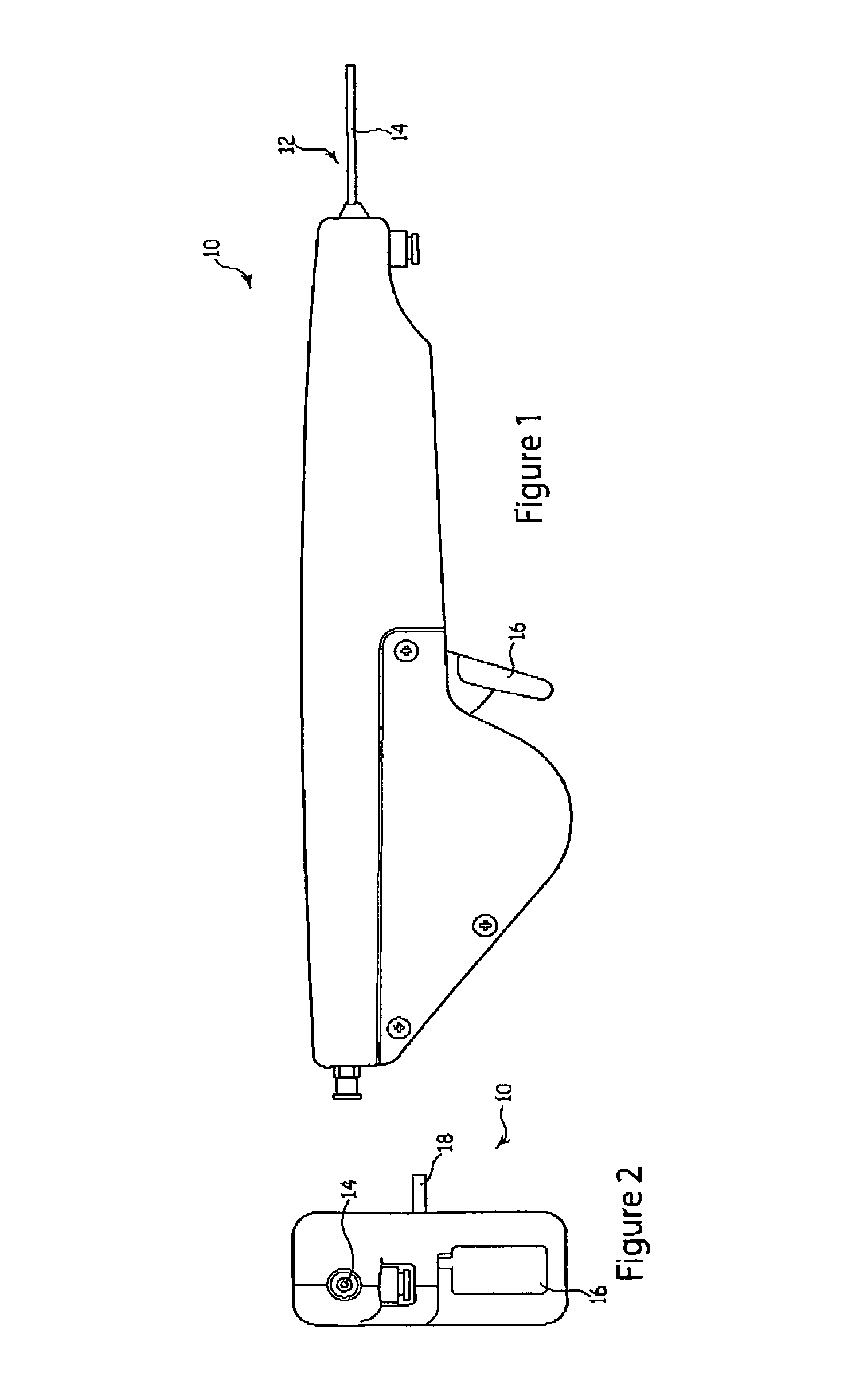
[0044]Referring to FIG. 1, there is shown a handle 10 for an introducer 12. This particular embodiment is designed to accommodate the applicant's Zilver™ stent introducer available from the applicant. As is described in more detail below, the handle 10 of this embodiment is designed to fit over the conventional handle of a Zilver™ introducer and operate the Zilver™ introducer in a manner analogous to similar introducers provided with a catheter assembly 14 having an outer sheath which houses an inner catheter and, in this particular example, a Zilver™ stent disposed on the inner catheter for deployment into the lumen of a patent.

[0045]The handle 10 is provided with a trigger 16 which can be pressed by a clinician, in a manner analogous to a gun trigger, in order to operate the handle 10 to deploy the stent.

[0046]Referring to FIG. 2, the handle 10 is shown in front elevational view, where it can be seen that there is provided a locking pin 18 on one side of the body of the handle 10 ...


PUM


Abstract

A deployment assembly (10) for an introducer used for introducing into a patient a stent or other device, the deployment assembly including a housing 30 carrying a sprung loaded (90) actuator (44,50). The actuator includes a toothed wheel (50) carrying a spool (48) around which a retraction strap (44) can be wound. The strap (44) is coupled to a body member (26) of the introducer and through this to the outer sheath (14) thereof. A trigger (16) is provided for operating the actuator (44, 50). When the trigger (16) is pressed, the actuator winds, under the force produced by the spring (90), the strap (44) to thereby retract the outer sheath (14) so as to expose and then deploy the device carried on the introducer. The mechanism is such that a surgeon need not expend his own energy to retract the outer sheath (14) since this force is provided by the spring (90). Furthermore, the spring (90) acts in a plane other than that of the direction of retraction of the sheath (14), which minimizes the risk of inadvertent movement of the introducer as the sheath (14) is being retracted.

Description

CROSS-REFERENCE TO RELATED APPLICATIONS[0001]This application claims priority of provisional application Ser. No. 61 / 133,767, filed Jul. 2, 2008.TECHNICAL FIELD[0002]The present invention relates to a deployment assembly for deploying one or more components of an endovascular introducer assembly, as well as to an introducer assembly and the components thereof.BACKGROUND OF THE INVENTION[0003]The art of endoluminal prosthesis is well developed, being used for the deployment of implants, prosthesis and other medical devices, as well as for administering drugs and diagnostic purposes.[0004]In particular in connection with the deployment of implants, prostheses and other medical devices, such introducers are typically provided with an outer sheath within which the device to be introduced and other necessary medical equipment is fed. In the case of a device being introduced into a patient, this is generally pre-loaded onto the introducer within the sheath. The sheath is then introduced e...

Claims


Application Information

Patent Timeline
Patent Type & Authority Patents(United States)
IPC IPC(8): A61B17/00A61F2/06A61F2/95A61B17/34A61M5/178A61F2/966
CPCA61F2/966A61F2002/9517A61B2017/00371A61B2017/347A61F2/95A61B2017/00367A61F2/9517
Inventor HANSEN, PALLE M.LOWINGER, JOHAN M.
Owner COOK MEDICAL TECH LLC
Why Eureka
Try Eureka