Contact-type sensors, however, are relatively unstable and of limited reliability due to the direct contact with the rotating shaft.
In addition, they are expensive and are thus commercially impractical for competitive use in many applications, such as automotive steering or transmission systems, for which torque sensors are sought.
Unfortunately, providing sufficient space for the requisite excitation and sensing coils on and around the device on which the sensor is used can create practical problems in applications where space is at a premium.
Also, such sensors may be impractically expensive for use on highly cost-competitive devices, such as in automotive applications.
Because magnetic fields, in the context of their measurement, are fungible, the sensors taught by the above and other prior art may be susceptible to other magnetic fields of external origin.
Furthermore, the nearby presence of a ferromagnetic structure may distort the shape and direction of the earth's magnetic field, creating a localized area in which the
magnetic flux is concentrated in an undesirable direction.
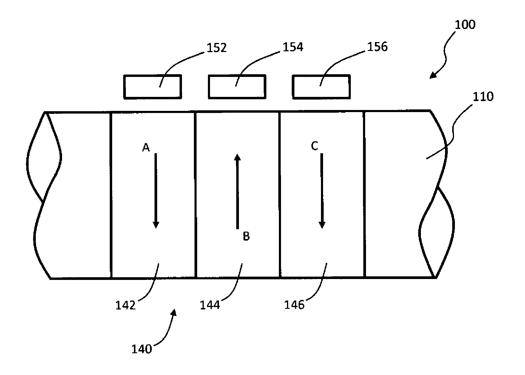
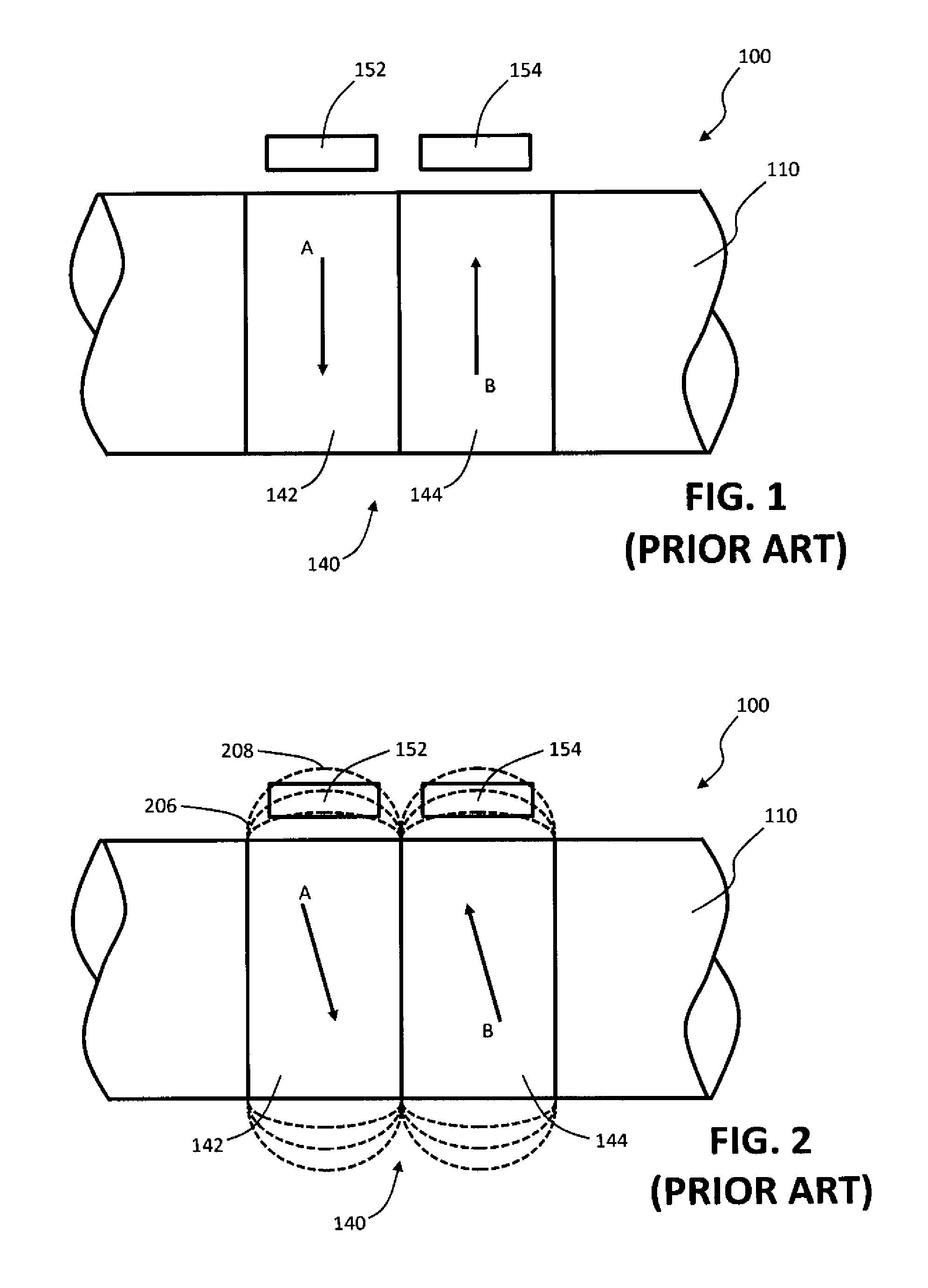
Sensors that are spaced from one another exhibit reduced common mode rejection efficiency, as the earth's magnetic field may be significantly distorted around ferromagnetic parts in and around the
torque sensor.
In practice, the configuration of the invention described in the '059 patent may be error-prone in the presence of locally divergent magnetic fields because the two magnetic field sensors experience different magnitudes of the divergent magnetic fields.
The difference in magnetic fields between the two magnetic field sensors originating from a near field source combines non-uniformly with torque induced magnetic fields and leads to a false torque value.
While the shielding method noted above can be effective for external magnetic fields perpendicular to the axial direction of a shield in the form of a tube, this shield is very vulnerable to external magnetic fields in the axial direction of the tube which is open at both ends.
Flux director structures typically operate by gathering the radial flux component of the torque dependent magnetic field, and are therefore well suited for rejecting axially directed flux of external origin, however, flux directors tend to be susceptible to external fields perpendicular to the axis of the shaft.
Such a combination, however, has other shortcomings that limit its desirability in many applications including cost and packaging within the design.
Frequently, demagnetization is not perfect, and there remains a remanant magnetic field in the column or shaft after the MPI process.
This relatively large external magnetic field can be directly transferred to the field sensors inside the shield, and can be non-uniformly summed with the torque-induced magnetic fields, corrupting the torque measurement.
This means that there is no totally effective way to protect or shield external magnetic fields propagating through the shaft with current techniques.
An additional
disadvantage of the shielding method is that any deformation of the shield device caused by
mechanical impact or
extreme temperature change can affect the relative position of the field sensors and the shield, which can lead to unbalancing of far field values between two sensor fields operating in pairs that are oppositely oriented.
This would result in compassing failure.
Furthermore, in most
torque sensor applications, packaging space is limited, and in many cases there is no room for a shield or flux director.
In addition, the added financial cost for those components is not insignificant because materials with high permeability tend to have high percentages of
nickel, the pricing of which is quite volatile.
The configuration of the invention described in the '953 publication can be error-prone in that its effectiveness is based on the assumption that noise-induced magnetic fields decrease linearly as distance from the noise source increases.
In practice, however, noise-induced magnetic gradients are typically non-linear.

