Laminated coil

a technology of laminated coils and coils, applied in the direction of coils, transformers/inductance details, electrical devices, etc., can solve the problem of limited electrical current flow, and achieve the effect of enhancing the radiation property of laminated coils

Inactive Publication Date: 2014-11-25
HITACHI METALS LTD
View PDF8 Cites 3 Cited by
  • Summary
  • Abstract
  • Description
  • Claims
  • Application Information

AI Technical Summary

Benefits of technology

[0008]In the coils having the above-mentioned configuration, the whole length of the coil located interiorly is shorter than that of the coil located exteriorly, thus electrical resistance of the coil located interiorly becomes relatively lowered, and electrical current becomes concentrated at the coil located interiorly, so that heat generation due to Joule heat in the coil located interiorly becomes larger than that in the coil located exteriorly. In addition, the coil located interiorly is surrounded by the coil located exteriorly over the whole periphery thereof thus it has a lower radiation property than the coil located exteriorly, and consequently electrical current allowed to flow is limited due to increase in temperature of the coil located interiorly.
[0010]Furthermore, the coils located interiorly and exteriorly are covered with an insulating material such as polyimide for insulating between the coils, and the insulating material has a thermal resistance higher than a conductive metal constituting the coils such as copper, aluminum. Accordingly, in case of allowing heat generated in the coil located interiorly to escape toward the direction of the outer periphery, an insulating material at the outer peripheral side of the coil located interiorly and insulating materials at the inner and outer peripheral sides of the coil located exteriorly are included in the radiation pathway, thus the radiation property of the coil located interiorly is further lowered.
[0022]According to one embodiment of the invention, a laminated coil is constructed such that a first circular conductive plate and a second circular conductive plate are laminated with each other in a central axis line direction with each connection part of the first and second conductive plates facing each other. In addition, when the first and second circular conductive plates are laminated, a second circular arc part of the first plate is arranged outside in a radial direction of a first circular arc part of the second plate, and a second circular arc part of the second plate is arranged outside in the radial direction of a first circular arc part of the first plate. Here the first circular arc parts of the first and second plates arranged inside in the radial direction are surrounded by the second circular arc parts arranged outside in the radial direction, they have a radiation property lower than the second circular arc parts. However, heat generated in the first circular arc parts (inside) is conducted to the second circular arc parts (outside) and dissipated therefrom to the periphery, whereby it is possible to prevent heat from being confined in the first circular arc parts (inside). Thereby, the radiation property of the laminated coil can be enhanced.

Problems solved by technology

In addition, the coil located interiorly is surrounded by the coil located exteriorly over the whole periphery thereof thus it has a lower radiation property than the coil located exteriorly, and consequently electrical current allowed to flow is limited due to increase in temperature of the coil located interiorly.

Method used


Image

  • Laminated coil
  • Laminated coil
  • Laminated coil

Examples


first embodiment

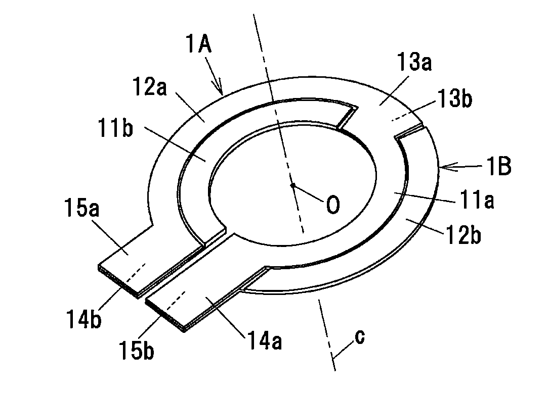
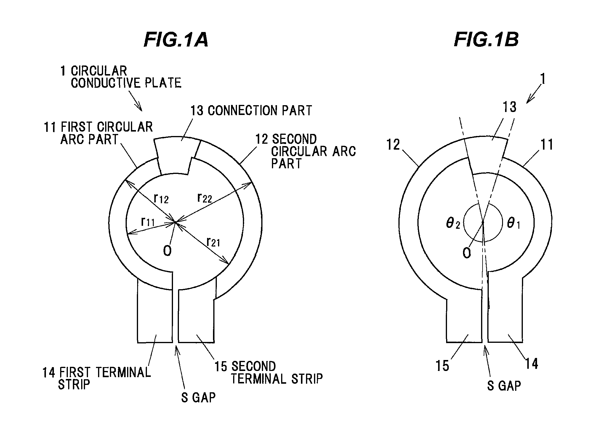
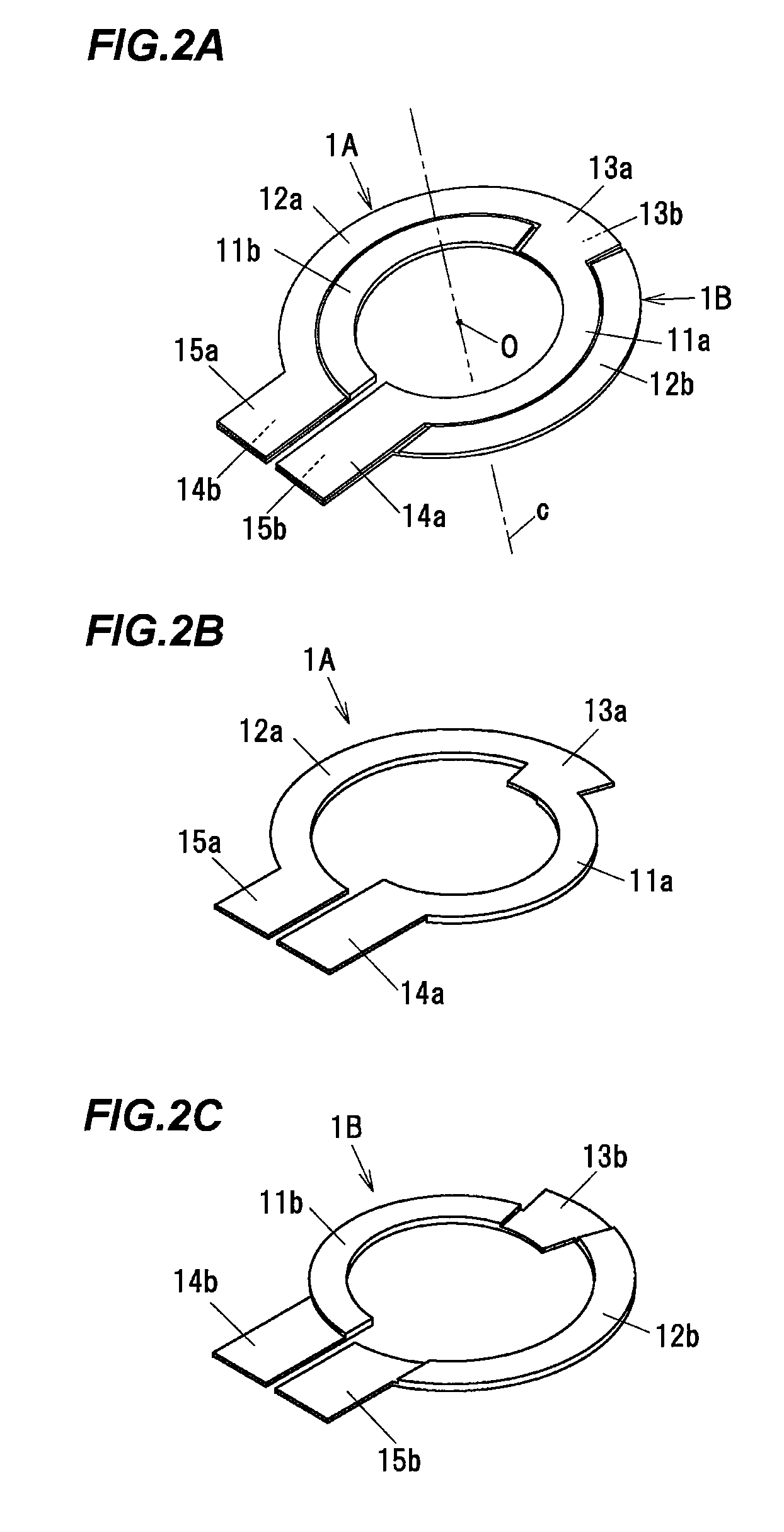
[0045]FIGS. 1A and 1B are a front elevation view and a back elevation view schematically showing an example of a configuration of a circular conductive plate constituting a laminated coil according to one embodiment of the invention respectively.

[0046]A circular conductive plate 1 is composed of a conductive metal such as copper, aluminum and is formed in a flat plate-like shape. The circular conductive plate 1 integrally includes a first circular arc part 11, a second circular arc part 12, a connection part 13 that interconnects the first circular arc part 11 and the second circular arc part 12, a first terminal strip 14 formed so as to be continuous with the first circular arc part 11, and a second terminal strip 15 formed so as to be continuous with the second circular arc part 12. In addition, the circular conductive plate 1 is formed in a circular shape except for a gap (S) having a slit-like shape formed between the first terminal strip 14 and the second terminal strip 15.

[004...

second embodiment

[0086]Hereinafter, the second embodiment of the invention will be explained referring to FIG. 7 and FIG. 8.

[0087]FIG. 7A is a front elevation view schematically showing a laminated coil 200 according to the second embodiment of the invention, FIG. 7B is a cross-sectional view taken along the line F-F in FIG. 7A, FIG. 7C is a cross-sectional view taken along the line G-G in FIG. 7A and FIG. 7D is a cross-sectional view taken along the line H-H in FIG. 7A. Further, in FIGS. 7B to 7D, a dimension in a thickness direction is expressed with exaggeration in comparison with a dimension in a radial direction for convenience of explanation.

[0088]The laminated coil 200 includes a first coil part 201, a second coil part 202 and a third coil part 203, and has a configuration that the first to third coil parts 201 to 203 are laminated with each other in an axis direction. The first to third coil parts 201 to 203 have a flat plate-like shape and have a configuration that an insulating layer 20 in...


PUM

PropertyMeasurementUnit
distanceaaaaaaaaaa
external radiusaaaaaaaaaa
distanceaaaaaaaaaa

Abstract

A laminated coil includes a plurality of circular conductive plates in the form of a flat plate, each of the circular conductive plates being laminated via an insulating material in an axis direction. The plurality of circular conductive plates each include a plurality of concentric circular arc parts having different inner diameter and outer diameter from each other, and a connection part interconnecting the plurality of circular arc parts. The plurality of circular conductive plates are arranged such that the connection parts thereof face each other and the circular arc parts thereof are juxtaposed to each other in a radial direction.

Description

[0001]The present application is based on Japanese patent application No. 2011-203083 filed on Sep. 16, 2011, the entire contents of which are incorporated herein by reference.BACKGROUND OF THE INVENTION[0002]1. Field of the Invention[0003]This invention relates to a laminated coil, in particular, this invention relates to a laminated coil configured to have a structure that a plurality of circular conductive plates are laminated in an axis direction.[0004]2. Description of the Related Art[0005]A coil is known that has a configuration obtained by winding plural rectangular wires in an axis direction (for example, refer to JP-A-H9-306757 and JP-A-2010-10176).[0006]A short height-type laminated coil described in JP-A-H9-306757 has a configuration that a first coil and a second coil formed by winding rectangular wires in an axis direction, the coils having three turns respectively, are arranged so as to be formed in a concentric shape and be juxtaposed to each other.[0007]A multiple co...

Claims


Application Information

Patent Timeline
Patent Type & Authority Patents(United States)
IPC IPC(8): H01F27/30H01F27/28H01F5/00H01F27/32
CPCH01F5/00H01F27/2847H01F27/303H01F27/323
Inventor YAMAMOTO, SATOSHI
Owner HITACHI METALS LTD
Why Eureka
Try Eureka