Portable thermal image emergency exit marking device for firefighters

Inactive Publication Date: 2014-11-25
RAMIREZ ROLAND
View PDF13 Cites 17 Cited by
  • Summary
  • Abstract
  • Description
  • Claims
  • Application Information

AI Technical Summary

Benefits of technology

[0020]The present invention overcomes the aforementioned problems and is distinguished over the prior art in general, and these patents in particular, by a portable emergency exit marking device for use by firefighters and rescue personnel that includes a polygonal housing having electrical heating elements on side panels in the form of letters or symbols that form infrared heat generating words or symbols indicating exit routes that are clearly visible by a thermal imaging camera, a flashing strobe light, and an audible alarm, to guide firefighters to the exit of a burning smoke-filled building. The configuration of the

Problems solved by technology

Firefighters and other emergency personnel operating inside a smoke-filled or burning building or other structure often become disorientated or lost due to the heat and severely limited visibility in the dense smoke and darkness, and many lives are lost each year because they become trapped by the structure are otherwise unable to escape due to operating on a limited air supply because they are unable to find an exit from the burning structure.
However, the intensity of light generated by a flashlights and lanterns typically cannot effectively penetrate heavy smoke or flame.
These types of device are also typically not effective due to the limited visibility inside the burning building is limited because of the heavy smoke or flame.
Although these prior are exit indicating devices may be effective for their intended purposes, the existing exit indicating devices do not lend themselves to effectively identify the exit in dense smoke and darkness or flame.
Although thermal imaging cameras (TIC's) significantly increase the visibility and display thermal patterns that indica

Method used


Image

  • Portable thermal image emergency exit marking device for firefighters
  • Portable thermal image emergency exit marking device for firefighters
  • Portable thermal image emergency exit marking device for firefighters

Examples


Embodiment Construction

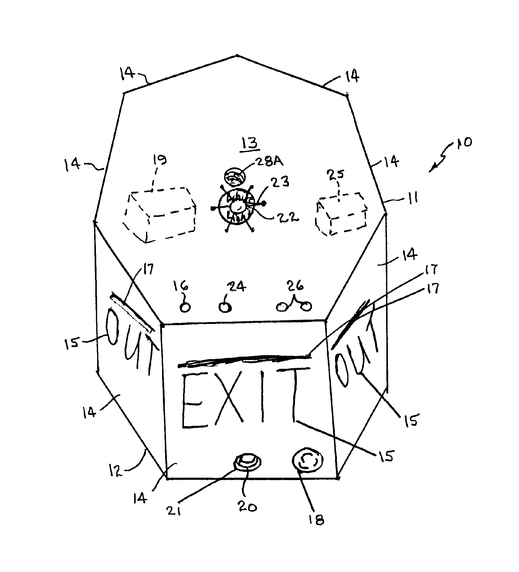
[0024]The present invention is directed toward a portable emergency exit marking device for use by firefighters and rescue personnel that includes electrical heating elements shaped to form infrared heat generating symbols or words indicating exit routes that are visible by a thermal imaging camera, a flashing strobe light, and an audible alarm, to guide firefighters to the exit of a burning smoke-filled building. The making device may also have a ring for releasably receiving one end of a rope that can be extended from the device to an exit of the burning structure and followed to exit the burning structure.

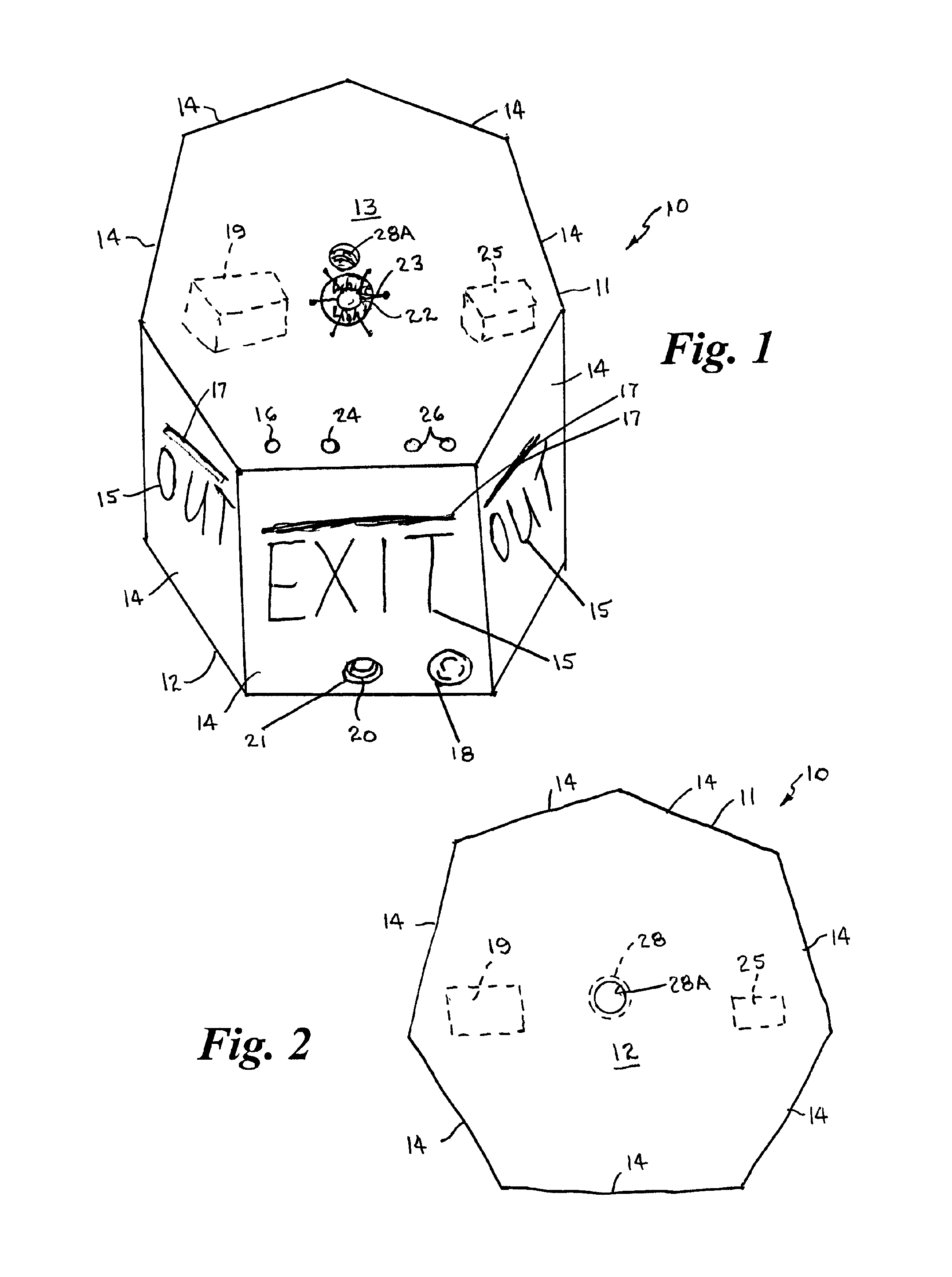
[0025]Referring now to FIG. 1 of the drawings, the portable emergency exit marking device 10 includes a polygonal housing 11 having a bottom panel 12, a top panel 13 and a plurality of peripheral side panels 14. The polygonal housing 11 is formed of a suitable fireproof heat and shock resistant material, capable of withstanding damage by fire, heat, and other stresses to which i...


PUM


Abstract

A portable thermal image emergency exit marking device for use by firefighters and rescue personnel includes a polygonal housing having electrical heating elements on side panels that are shaped to form infrared heat generating words or symbols indicating an escape exit which are clearly visible by a thermal imaging camera, a flashing strobe light, and an audible alarm, to guide firefighters to the exit of a burning smoke-filled building. The configuration of the infrared heating elements avoids confusion and clearly distinguishes the words or symbols from other hot spots, heat emitting objects, and burning objects in the environment of the burning structure. An accessory adjustably supports the marking device at various heights above the floor surface when desired. The housing may have a ring for connecting a rope that can be extended from the housing to an exit of the burning structure and followed to exit the burning structure.

Description

CROSS REFERENCE TO RELATED APPLICATION[0001]This application claims priority of U.S. Provisional Application Ser. No. 61 / 389,723, filed Oct. 5, 2010.BACKGROUND OF THE INVENTION[0002]1. Field of the Invention[0003]This invention relates generally to firefighting equipment and infrared signage devices, and more particularly to a portable emergency exit marking device which includes electrical heating elements in the form of letters forming infrared exit wording that is visible by a thermal imaging camera, an audible alarm, and a blinking light for guiding firefighters to the exit of a burning smoke-filled building.[0004]2. Background Art[0005]Firefighters and other emergency personnel operating inside a smoke-filled or burning building or other structure often become disorientated or lost due to the heat and severely limited visibility in the dense smoke and darkness, and many lives are lost each year because they become trapped by the structure are otherwise unable to escape due to o...

Claims


Application Information

Patent Timeline
IPC IPC(8): G08B17/00
CPCG08B7/062
Inventor RAMIREZ, ROLAND
Owner RAMIREZ ROLAND
Why Eureka
Try Eureka