
Medical device wireless network architectures

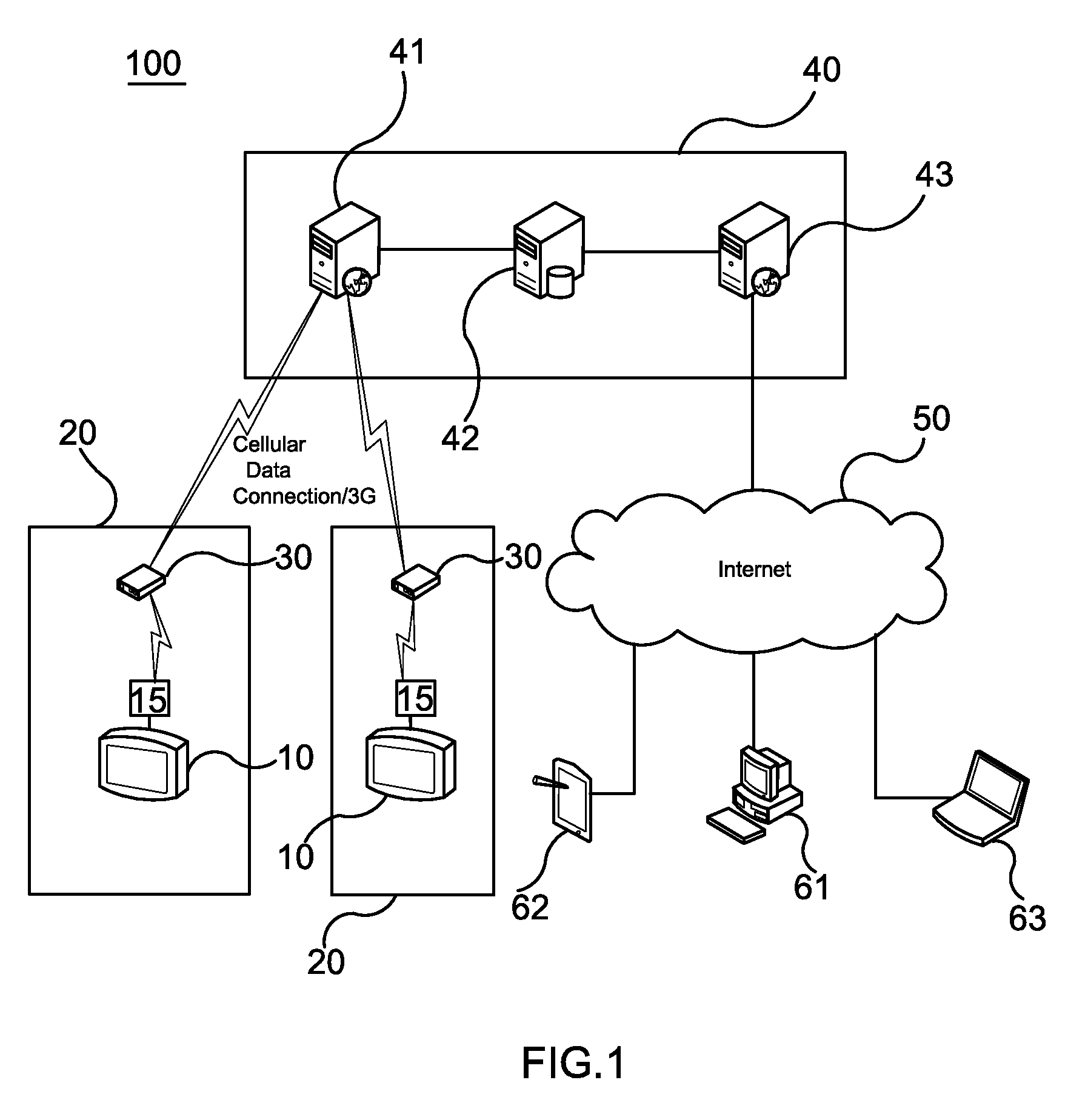
a wireless network and medical device technology, applied in the field of network architectures, can solve the problems of affecting the response time of care givers to significant health conditions and events, affecting the security of local area network access, and presenting a number of difficulties in implementing such centralized monitoring systems using wireless networks

Active Publication Date: 2014-11-25
KPR U S LLC
View PDF219 Cites 30 Cited by
  • Summary
  • Abstract
  • Description
  • Claims
  • Application Information

AI Technical Summary

Benefits of technology

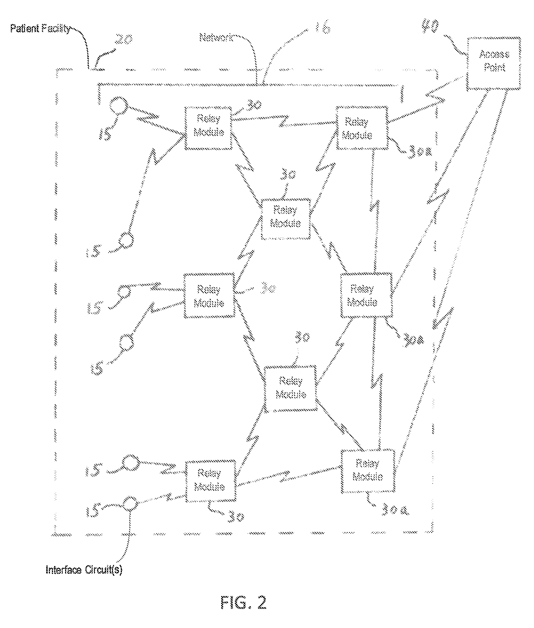
The wireless relay module described in the patent text can communicate with other wireless relay modules and through the internet-accessible wireless network. It also has a second receiver for receiving data and commands from the network and can communicate with specific medical devices. This allows for more efficient and effective communication in medical applications using wireless technology.

Problems solved by technology

Moreover, response times by care givers to significant health conditions and events can be critical.
Implementing such centralized monitoring systems using wireless networks may present a number of difficulties.
However, as such networks are typically already in place in facilities to support a variety of other functions (for example, physician access to electronic medical records (EMRs), facility administrative systems and other functions), it is often undesirable to secure sufficient local area network access for the purpose of providing centralized monitoring.
Moreover, when a patient is located remotely from a critical care health service center (for example, at home), access to traditional local area network facilities such as a WiFi network may be unavailable or not sufficiently reliable to support critical care monitoring applications.
However, transmission ranges between individual ZIGBEE transceivers are generally limited to no more than several hundred feet.
As a consequence, such networks are generally unusable for centralized monitoring locations located off-site.

Method used


Image

  • Medical device wireless network architectures
  • Medical device wireless network architectures
  • Medical device wireless network architectures

Examples


Embodiment Construction

[0017]Reference will now be made in detail to exemplary embodiments of the invention, including the best modes contemplated by the inventors for carrying out the invention. Examples of these exemplary embodiments are illustrated in the accompanying drawings. While the invention is described in conjunction with these embodiments, it will be understood that it is not intended to limit the invention to the described embodiments. Rather, the invention is also intended to cover alternatives, modifications, and equivalents as may be included within the spirit and scope of the invention as defined by the appended claims.

[0018]In the following description, specific details are set forth in order to provide a thorough understanding of the present invention. The present invention may be practiced without some or all of these specific details. In other instances, well-known aspects have not been described in detail in order not to unnecessarily obscure the present invention.

[0019]For the purpo...


PUM


Abstract

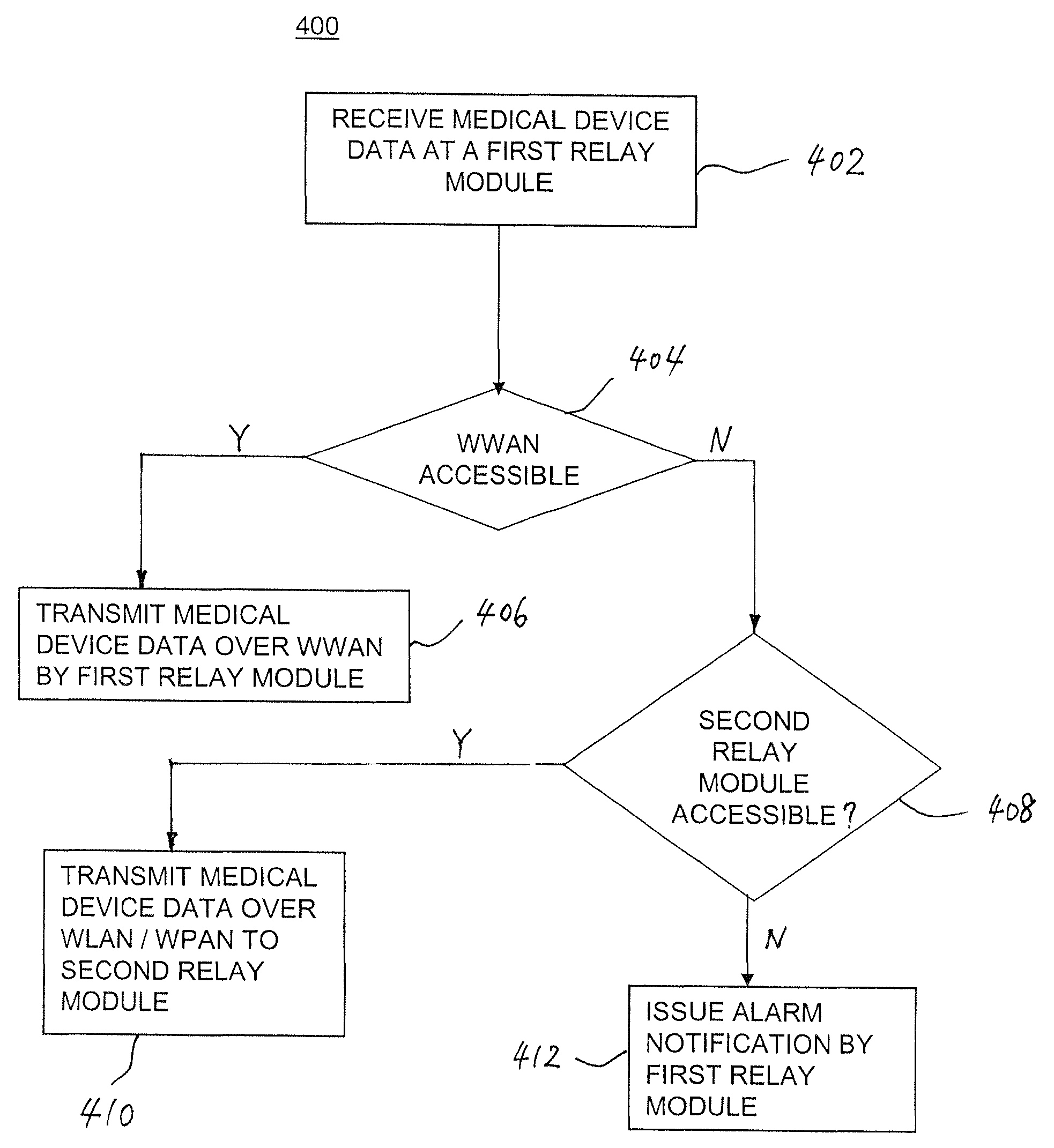
An architecture for networked communications between a series of medical devices and a remote monitoring device. An interface circuit coupled to each medical device communicates with one of a plurality of relay modules via a wireless relay network. The relay modules communicate with the remote monitoring device over an internet-accessible wireless communication network. Each relay module includes a receiver coupled to the wireless relay network, a first transmitter coupled to the wireless relay network, a second transmitter coupled to the internet-accessible wireless communications network; and a controller. The controller determines a status of the internet-accessible wireless communications network. When the status indicates that the internet-accessible wireless communications network is accessible to the wireless relay module, the second transmitter is selected for transmitting medical device data. When the internet-accessible wireless communications network is not accessible, the first transmitter is selected for transmitting the data to another wireless relay module.

Description

RELATED APPLICATION[0001]This application is related to U.S. application Ser. No. 13 / 006,769, now issued as U.S. Pat. No. 8,818,260, filed Jan. 14, 2011, entitled “Wireless Relay Module for Remote Monitoring Systems.”FIELD OF THE INVENTION[0002]The present application is directed to network architectures for providing networked communications between a series of medical devices and remote monitoring devices, and more particularly, to network architectures for providing networked communications between a series of medical devices and remote monitoring devices via wireless relay networks and internet-accessible wireless communications networks.BACKGROUND OF THE INVENTION[0003]In critical care and home care health service centers including hospitals, clinics, assisted living centers and the like, care giver-patient interaction time is at a premium. Moreover, response times by care givers to significant health conditions and events can be critical. Systems of centralized monitoring have...

Claims


Application Information

Patent Timeline
Patent Type & Authority Patents(United States)
IPC IPC(8): G06F19/00H04B7/14G16H40/67
CPCG06F19/3418G16H40/67G07F17/0092G16Z99/00
Inventor GAINES, ROBERT B.WIESNER, JOEL D.HOLSTE, JOHN
Owner KPR U S LLC
Learn More