Position detection system, position detection method, program, object determination system and object determination method

a technology of position detection and object determination, which is applied in the field of position detection system, position detection method, program, object determination system and object determination method, can solve the problem of decreasing the recognition rate and achieve the effect of more accurate detection of the hand or finger of the operator

Active Publication Date: 2014-11-25
SONY CORP
View PDF14 Cites 137 Cited by
  • Summary
  • Abstract
  • Description
  • Claims
  • Application Information

AI Technical Summary

Benefits of technology

[0008]In light of the foregoing, it is desirable to provide a novel and improved position detection system, a position detection method, a program, an object determination system and an object determination method capable of detecting an object such as the band or finger of an operator more accurately.
[0010]In this configuration, during emission of the electromagnetic wave by the electromagnetic wave emission unit, the object existing between the electromagnetic wave emission unit and the projection plane blocks the electromagnetic wave, and therefore the projection plane on which a projected image of the object is formed is captured by the imaging unit. The electromagnetic wave emitted from the electromagnetic wave emission unit reaches a background portion different from the projected image of the object on the projection plane. On the other hand, during no emission of the electromagnetic wave by the electromagnetic wave emission unit, the electromagnetic wave emitted from the electromagnetic wave emission unit does not reach the projection plane at all. Accordingly, the projected image detection section can detect the projected image of the object based on a difference between the image captured during emission of the electromagnetic wave and the image captured during no emission of the electromagnetic wave. Further, a formation position of the projected image of the object depends on the positional relationship of the electromagnetic wave emission unit and the object. Thus, the position detection section can rationally detect the position of the object based on the formation position of the projected image of the object detected by the projected image detection section.
[0024]According to the embodiments of the present invention described above, it is possible to detect an object such as the hand or finger of an operator more accurately.

Problems solved by technology

Therefore, the method according to related art that uses an image captured during non-operation by an operator as a reference image has a drawback that the recognition rate for the hand or finger of the operator decreases if there is a change in environment from the time when the reference image is captured.

Method used


Image

  • Position detection system, position detection method, program, object determination system and object determination method
  • Position detection system, position detection method, program, object determination system and object determination method
  • Position detection system, position detection method, program, object determination system and object determination method

Examples


first embodiment

(1) First Embodiment

[0060](1-1) Circumstances of Development of the First Embodiment

[0061]Various interfaces that capture the image of an operator by an imaging unit, extract the hand, finger or the like of the operator from the captured image and detect the motion (gesture) of the extracted hand or finger as an input operation have been proposed heretofore.

[0062]In order to appropriately detect the input operation of an operator in such interfaces, it is important to efficiently and accurately extract the hand, finger or the like of the operator from a background image. However, the background image can contain the body image of the operator or the background image is not static in some cases. In this case, it is difficult to appropriately detect the hand, finger or the like of the operator from the background image. Further, lighting conditions can vary, and the recognition rate for the input operation decreases significantly in this case also.

[0063]Given such circumstances, a pos...

second embodiment

(2) Second Embodiment

[0152]The position detection system 1 according to the first embodiment of the present invention is described in the foregoing. In the following, a second embodiment of the present invention is described with reference to FIGS. 9 to 14 after describing the circumstances of development of the second embodiment.

[0153](2-1) Circumstances of Development of the Second Embodiment

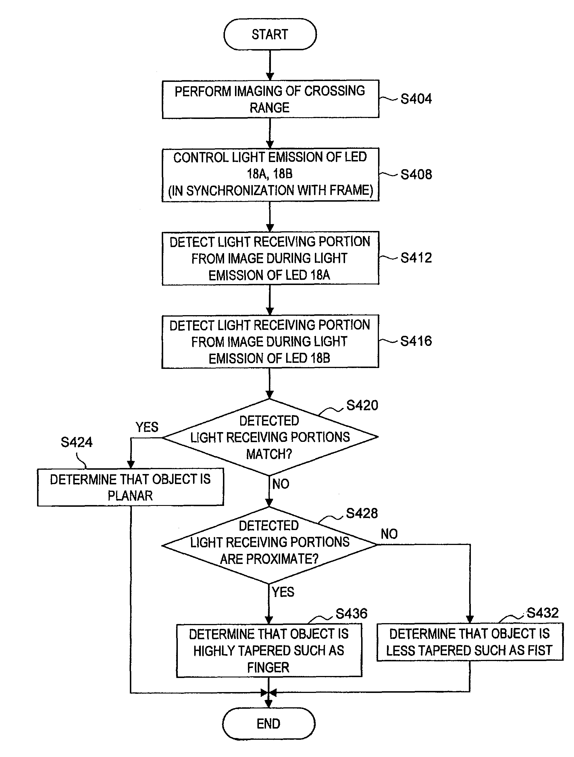
[0154]Various interfaces that capture the image of an operator by an imaging unit, extract an operator body from the captured image and detect the motion (gesture) of the extracted operator body as an input operation have been proposed heretofore. The operator body is assumed to be an operator's finger and a stick having a tapered three-dimensional shape and so on.

[0155]In order to appropriately detect the input operation of an operator in such interfaces, it is important to efficiently and accurately extract an object having a specific three-dimensional shape such as an operator's finger and ...


PUM


Abstract

There is provided a position detection system including an imaging unit to capture an image of a projection plane of an electromagnetic wave, an electromagnetic wave emission unit to emit the electromagnetic wave to the projection plane, a control unit to control emission of the electromagnetic wave by the electromagnetic wave emission unit, and a position detection unit including a projected image detection section to detect a projected image of an object existing between the electromagnetic wave emission unit and the projection plane based on a difference between an image of the projection plane captured during emission of the electromagnetic wave by the electromagnetic wave emission unit and an image of the projection plane captured during no emission of the electromagnetic wave, and a position detection section to detect a position of the object based on a position of the projected image of the object.

Description

CROSS REFERENCES TO RELATED APPLICATIONS[0001]The present invention contains subject matter related to Japanese Patent Application JP2008-098615 filed in the Japan Patent Office on Apr. 4, 2008, the entire contents of which being incorporated herein by reference.BACKGROUND OF THE INVENTION[0002]1. Field of the Invention[0003]The present invention relates to a position detection system, a position detection method, a program, an object determination system and an object determination method.[0004]2. Description of the Related Art[0005]Studies of new interfaces for inputting information to information processing units such as a PC (Personal Computer) and a cellular phone are widely conducted today. For example, an interface is proposed that captures the image of an operator by an imaging unit, extracts the hand, finger or the like of the operator from the captured image and detects the motion (gesture) of the extracted hand or finger as an input operation.[0006]In order to appropriate...

Claims


Application Information

Patent Timeline
Patent Type & Authority Patents(United States)
IPC IPC(8): G06T7/00G06F3/01G06F3/042G06K9/46
CPCG06T7/004G06F3/0425G06F3/017G06T2207/10152G06T7/70
Inventor REKIMOTO, JUNICHI
Owner SONY CORP
Why Eureka
Try Eureka