Restraint system for elevated surface tiles

a technology of restricting system and elevated surface, which is applied in the direction of flooring, building roof, building repairs, etc., can solve the problems of limited safe obtainable height of the support pedestal, insufficient structural stability of the support structure, and inability to safely use the support structure, etc., to achieve the effect of improving structural stability

Active Publication Date: 2014-12-02
UNITED CONSTR PROD LLC
View PDF114 Cites 43 Cited by
  • Summary
  • Abstract
  • Description
  • Claims
  • Application Information

AI Technical Summary

Benefits of technology

[0009]It is therefore an objective to provide a support structure for an elevated surface, where the support structure has improved structural stability. It is also an objective to provide a support structure that can enable the construction of an elevated surface having an increased height above the fixed surface as compared to existing support structures, particularly in areas that are prone to disruptive vibrations.
[0013]In accordance with the foregoing embodiments and aspects, the support structure can provide increased structural stability. In one aspect, the support structure can be used to support elevated surfaces in seismically active geographic areas or in other areas where disruptive vibrations may occur, such as a train platform. Through interconnection of the support pedestals, the support pedestals can move in unison during a seismic event or other vibratory disruption to maintain the desired spacing between the support pedestals, and therefore continue to safely support surface tiles placed on the support pedestals and maintain the integrity of the building surface.

Problems solved by technology

One problem associated with some support structures for elevated surfaces is that the support structures may not provide adequate structural stability in certain unstable environments.
As a result, the support structures may not be suitable for use in certain seismically active geographic areas, high wind areas or other locations that may be subject to disruptive vibrations of the fixed surface.
Another problem associated with some support structures for elevated surfaces is that the safely obtainable height of the support pedestals may be limited due to the increasing instability of the support pedestals as the height of the pedestals, and hence the center of gravity of the pedestals, is increased.
The increased height of the center of gravity further compounds the problems associated with disruptive vibrations of the underlying surface.

Method used


Image

  • Restraint system for elevated surface tiles
  • Restraint system for elevated surface tiles
  • Restraint system for elevated surface tiles

Examples


Embodiment Construction

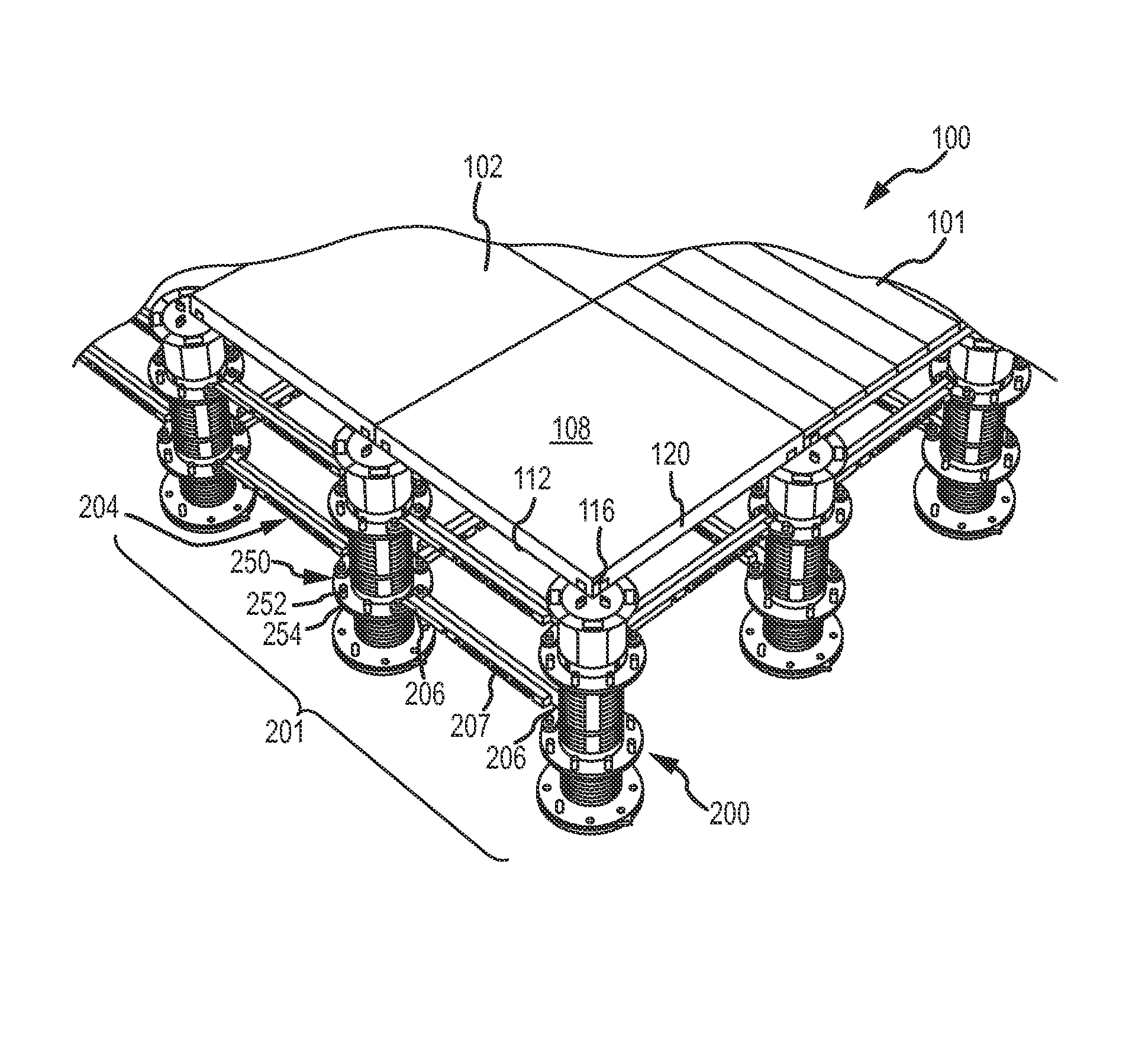
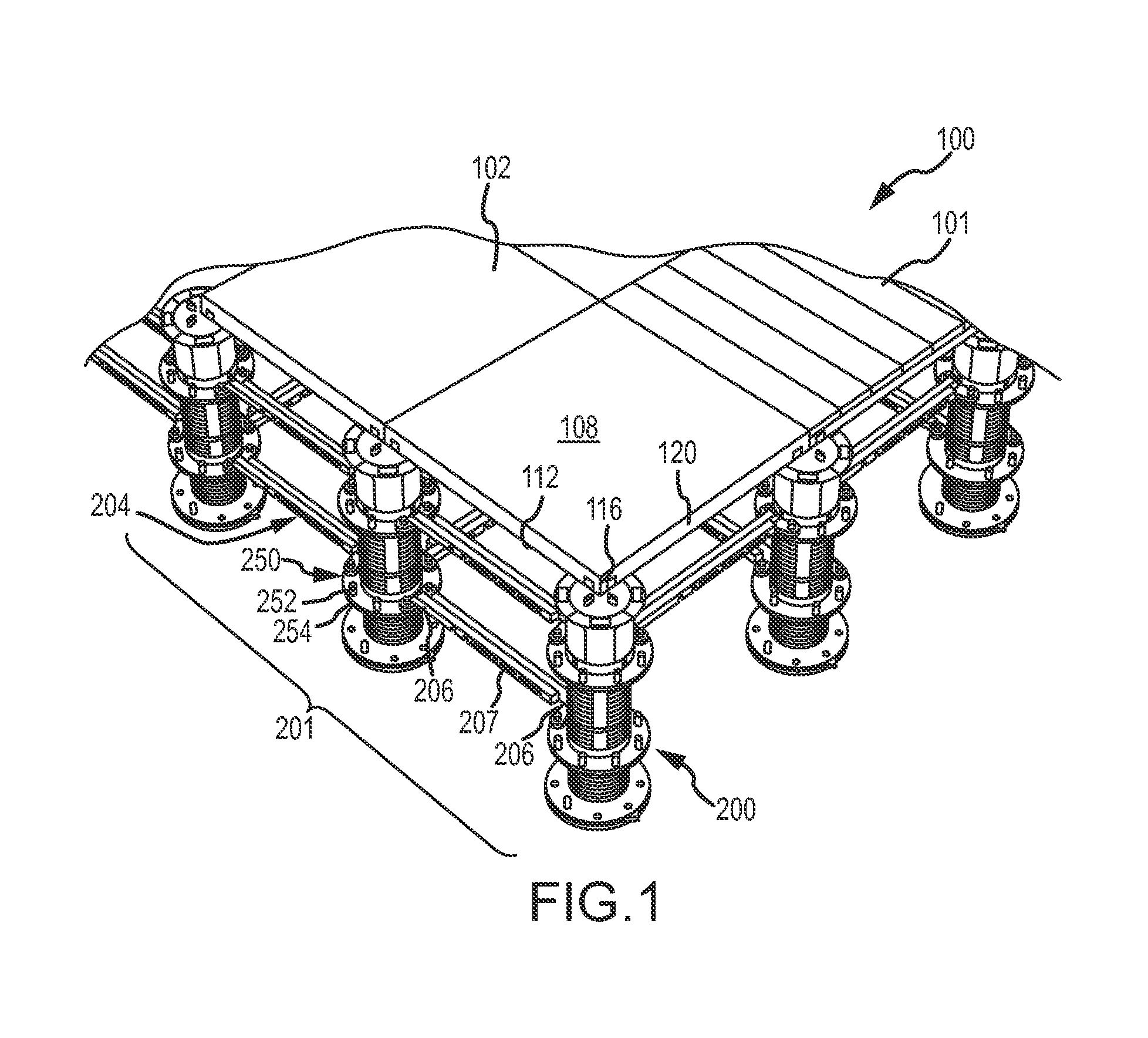
[0027]FIG. 1 illustrates a portion of an elevated building surface assembly 100 that includes a building surface 101 formed from a plurality of surface tiles 102. The surface tiles 102 are elevated above a fixed surface by a support structure 200 comprising a plurality of spaced-apart support pedestals 201 which are interconnected by a plurality of stabilizing braces 204. Each surface tile 102 may broadly include generally opposing top and bottom surfaces 108, 112, one or more corner portions 116, and one or more outer edge segments 120 disposed between adjacent corner portions 116. The surface tiles 102 can be comprised of virtually any material from which a building surface is constructed. Examples include, but are not limited to, slate tiles, natural stone tiles, composite tiles, concrete tiles (e.g., pavers), wooden deck tiles, particularly hardwood deck tiles, tiles of metal or fiberglass grating, porcelain, and the like.

[0028]The support pedestals 201 can be placed in a spaced...


PUM


Abstract

A support structure for elevating a building surface above a fixed surface including a plurality of support pedestals disposed in spaced-apart relation on the fixed surface, a plurality of stabilizing braces interconnecting adjacent of the plurality of support pedestals, and a plurality of restraint members. The restraint members include a mounting portion securable to one of the plurality of stabilizing braces and a restraint portion operatively attached to the mounting portion and securable to an outer edge segment of one or more of the surface tiles.

Description

BACKGROUND OF THE INVENTION[0001]1. Field of the Invention[0002]This invention relates to the field of support structures for supporting an elevated surface above a fixed surface, such as for elevated floors, decks and walkways.[0003]2. Description of Related Art[0004]Elevated building surfaces such as elevated floors, decks, terraces and walkways are desirable in many environments. One common system for creating such surfaces includes a plurality of surface tiles, such as concrete tiles (pavers), stone tiles, clay tiles, or wood tiles, and a plurality of spaced-apart support pedestals upon which the tiles are placed to be supported above a fixed surface. For example, in outdoor applications, the surface may be elevated above a fixed surface by the support pedestals to promote drainage, to provide a level structural surface for walking, and / or to prevent deterioration of or damage to the surface tiles. The pedestals can have a fixed height, or can have an adjustable height such as t...

Claims


Application Information

Patent Timeline
Patent Type & Authority Patents(United States)
IPC IPC(8): E04F15/02E04B1/00
CPCE04F15/02194E04F15/0247E04F15/02464
Inventor KUGLER, WILLIAM E.KNIGHT, III, STEPHEN J.VON-GUNTEN, LISA K.
Owner UNITED CONSTR PROD LLC
Why Eureka
Try Eureka