
Spacer and components therefor

a spacer and spacer technology, applied in the direction of valves, respirators, inhalators, etc., can solve the problems of increasing the resistance to flow, overly complex designs, and adding to the complexity, and achieve the effect of restricting the outside air

Active Publication Date: 2014-12-09
MEDICAL DEV INT
View PDF10 Cites 11 Cited by
  • Summary
  • Abstract
  • Description
  • Claims
  • Application Information

AI Technical Summary

Benefits of technology

The patent describes a device for controlling the flow of medicinal substances in a respiratory system. It has two main parts: a first part that opens during user inspiration to allow the medication to flow forward and closes during user expiration to prevent it from backflowing; and a second part that closes during user inspiration to prevent outside air from flowing into the device and opens during expiration to allow air to be expelled. This device helps to deliver medication to the lungs in a safe and effective way.

Problems solved by technology

However, if the patient is unable to co-ordinate spraying of the medication into their mouth (which is actuated by depressing a medication canister inside a housing of the inhaler), with a deep inspiratory breath, much of the medication may be deposited on the back of their mouth instead of being drawn deep into their lungs.
A disadvantage of prior art spacers such as the one mentioned above may be the use of two valves which both move during inspiration and expiration, potentially causing increased resistance to flow and leading to overly complex designs.
Another disadvantage with these types of spacers may be the need for ultrasonic welding of the chamber components, potentially adding to the complexity and reducing efficiency of assembly during manufacture.

Method used


Image

  • Spacer and components therefor
  • Spacer and components therefor
  • Spacer and components therefor

Examples


Embodiment Construction

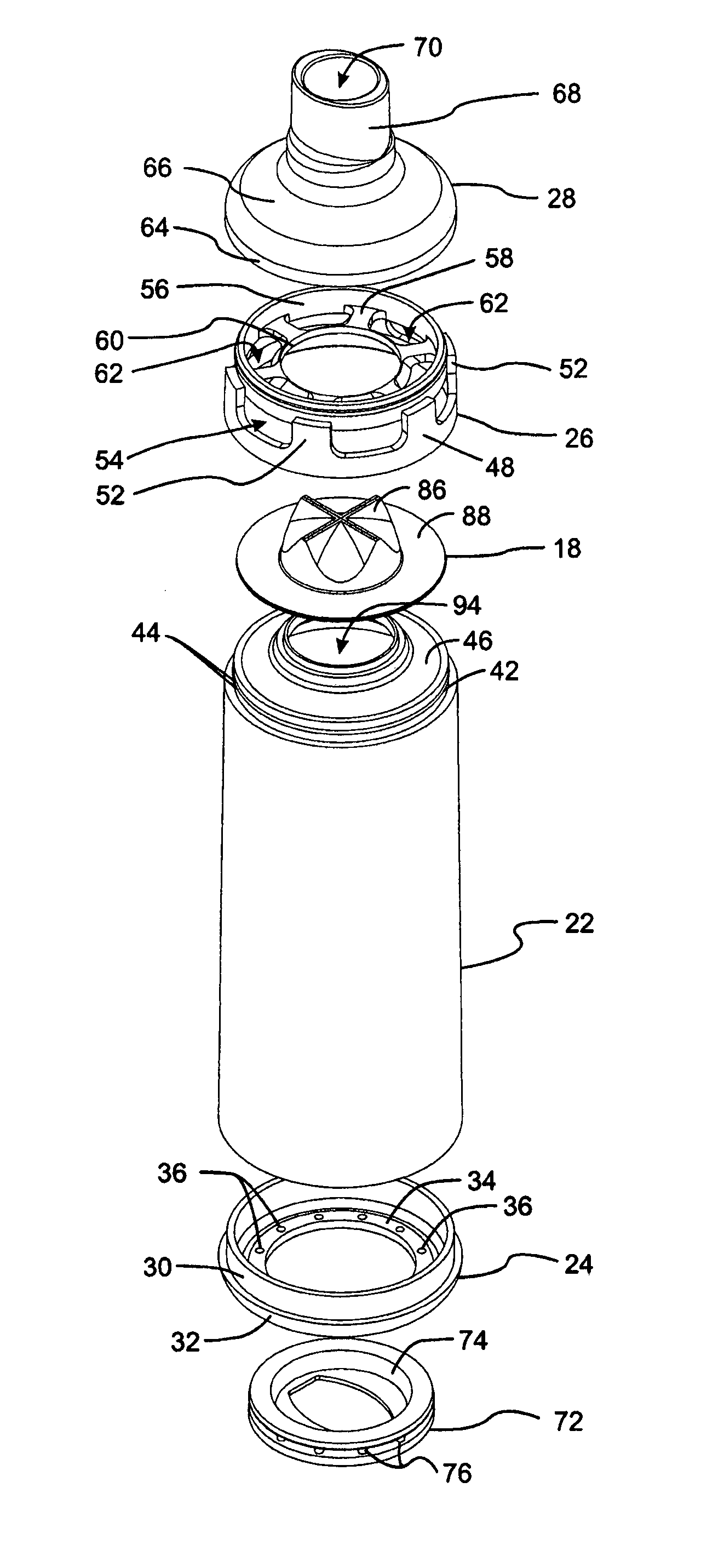
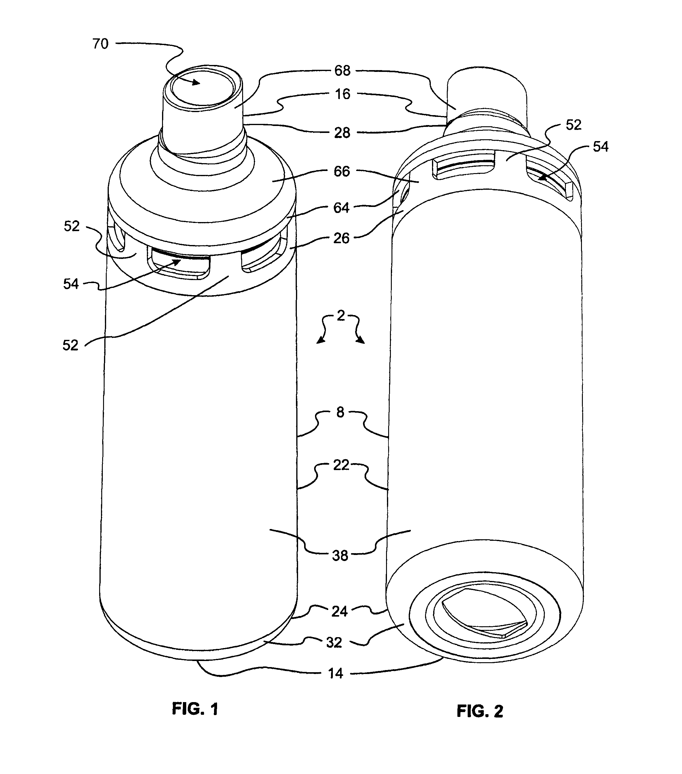
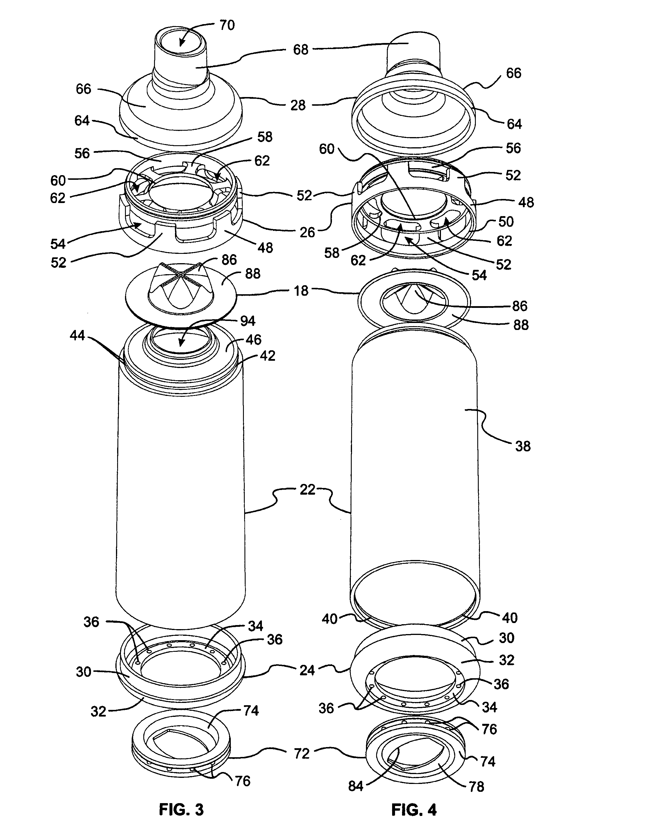
[0070]Referring to the drawings, there is shown a spacer, generally designated 2, which is suitable for delivering aerosolised medication 4 to a user 6 (see FIG. 21 in particular).

[0071]The spacer 2 comprises a Makrolon polycarbonate chamber 8 and a flow valve 18 located within the chamber 8.

[0072]The chamber 8 comprises:[0073]a first reservoir 10 and a second reservoir 12 (see FIGS. 20-22);[0074]an inlet 14 for admission of aerosolised or powdered medication 4 into the first reservoir 10;[0075]an outlet 16 for withdrawal of the medication 4 from the second reservoir 12; and[0076]a vent 20 for expulsion of air from the second reservoir 12.

[0077]The flow valve 18 is adapted to:[0078]allow forward-flow of the medication from the first reservoir 10 to the second reservoir 12 during user inspiration;[0079]substantially limit inflow of air through the vent 20 into the second reservoir 12 during user inspiration;[0080]substantially limit backflow of the medication or air from the second r...


PUM


Abstract

A spacer for delivering a medicinal substance is provided having a chamber having a tubular body defining a first reservoir, the top end of the body narrowing to define a single unobstructed central chamber aperture, a base for the body having an inlet for admission of the substance into the first reservoir, a vented member connected atop the body, a mouthpiece connected atop the vented member and partly defining a second reservoir, the mouthpiece having an outlet for withdrawal of the substance from the second reservoir The spacer also has a valve within the chamber having a self-supporting central domed portion and defining a central cross slit at its peak, the domed portion opening during inspiration and closing during expiration, and a flat ringed portion surrounding the domed portion with a circumferential free edge, the diameter of the ringed portion being approximately twice the diameter of the domed portion.

Description

TECHNICAL FIELD[0001]The present invention relates to a spacer and / or components therefor. In one particular aspect the invention relates to a flow valve for use in a spacer.BACKGROUND ART[0002]Any discussion of documents, devices, acts or knowledge in this specification is included to explain the context of the invention. It should not to be taken as an admission that any of the material forms a part of the prior art base or the common general knowledge in the relevant art in Australia or elsewhere on or before the priority date of the disclosure herein.[0003]Sufferers of asthma or chronic obstructive pulmonary disease (COPD) often use a metered dose inhaler in order to inhale a bronchodilatory drug such as Salbutimol into their lungs, thereby opening up their pathologically constricted airways. However, if the patient is unable to co-ordinate spraying of the medication into their mouth (which is actuated by depressing a medication canister inside a housing of the inhaler), with a ...

Claims


Application Information

Patent Timeline
Patent Type & Authority Patents(United States)
IPC IPC(8): A61M39/24A61M16/00A61M39/10A61M15/00
CPCA61M15/0086A61M15/009A61M15/0065A61M2039/1077A61M15/0016A61M16/208A61M39/24
Inventor EAGLE, ALLAN
Owner MEDICAL DEV INT
Learn More