Machine for flash-butt welding of rails

a technology of flashbutt welding and rails, which is applied in the field of welding, can solve the problems of insufficient length of flexible current-carrying jumpers, inability to make operation for pulling long rail sections at the required force, and limited length of jumpers, so as to improve the known design of machines and provide the stability of resistance of the machine electric circui

Inactive Publication Date: 2014-12-09
PATON INST OF ELECTRIC WELDING OF THE NAS OF UKRAINE
View PDF17 Cites 8 Cited by
  • Summary
  • Abstract
  • Description
  • Claims
  • Application Information

AI Technical Summary

Benefits of technology

[0008]The task of the invention is to improve the known designs of machines for the flash-butt welding of rails by modernization of an electric circuit of the machine due to adding the new elements, such as controlled drives connected to electric contacts-yokes, and a change in design of the upper part of the electric contacts-yoke by making holes in it and using guide rods, which pass through these holes, and also the mounting of a retaining spring on a lateral surface of each electric contacts-yoke. These improvements make it possible to provide the stability of resistance of the machine electric circuit during welding and to avoid the operation of electric contacts-yokes in fulfillment of auxiliary operations for pulling the long sections being welded on at a required force without changing the optimum welding conditions.

Problems solved by technology

The main drawback of the machine is an insufficient length of flexible current-carrying jumper which does not allow making operation for pulling the long rail sections at a required force.
This limited length of the jumpers is not enough for the welding of long sections under field conditions, when it is necessary to provide the pulling of the rail section to be welded on at a required force before the welding process proper by increasing the travel of rods of displacement and upsetting for a distance which exceeds greatly that of the parts displacement necessary directly for the welding process.
That leads to a significant increase in the resistance of the electric circuit of the welding machine, instability of the welding process and, as a consequence, to the appearance of non-quality welded rail joints.

Method used


Image

  • Machine for flash-butt welding of rails
  • Machine for flash-butt welding of rails
  • Machine for flash-butt welding of rails

Examples


Embodiment Construction

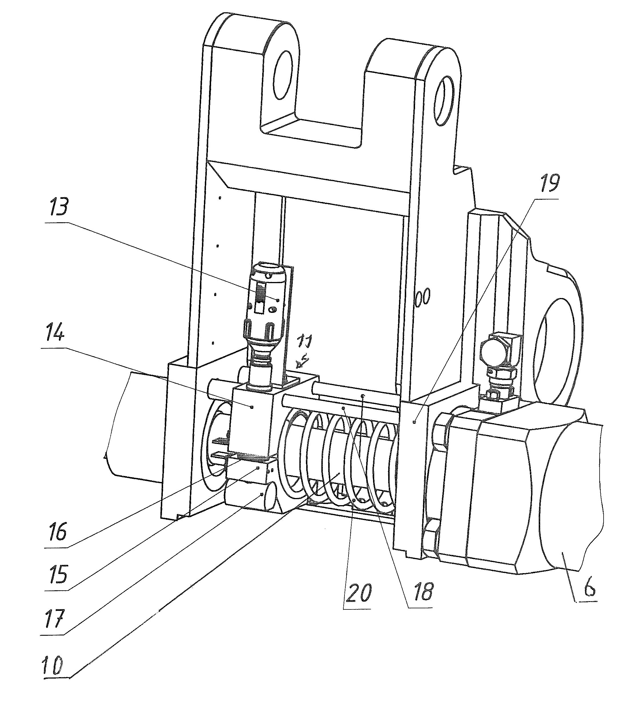
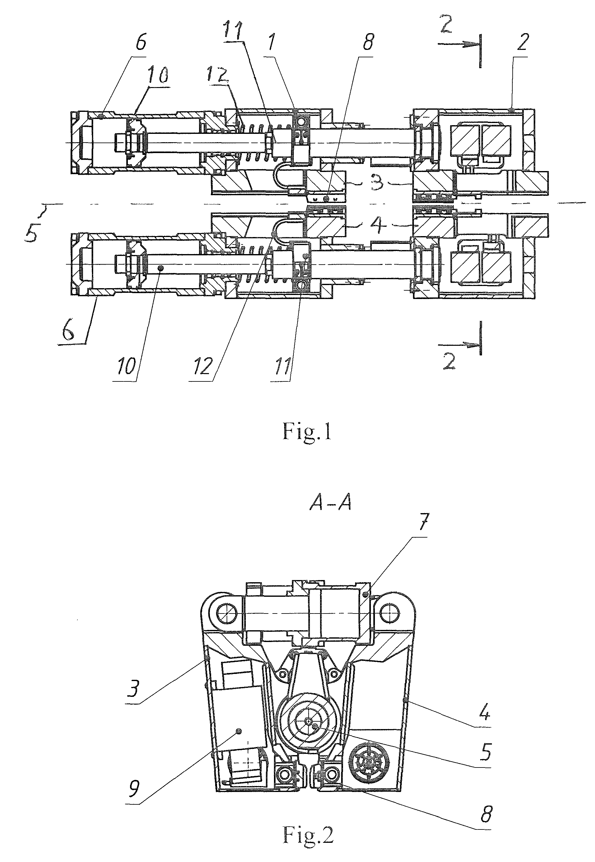
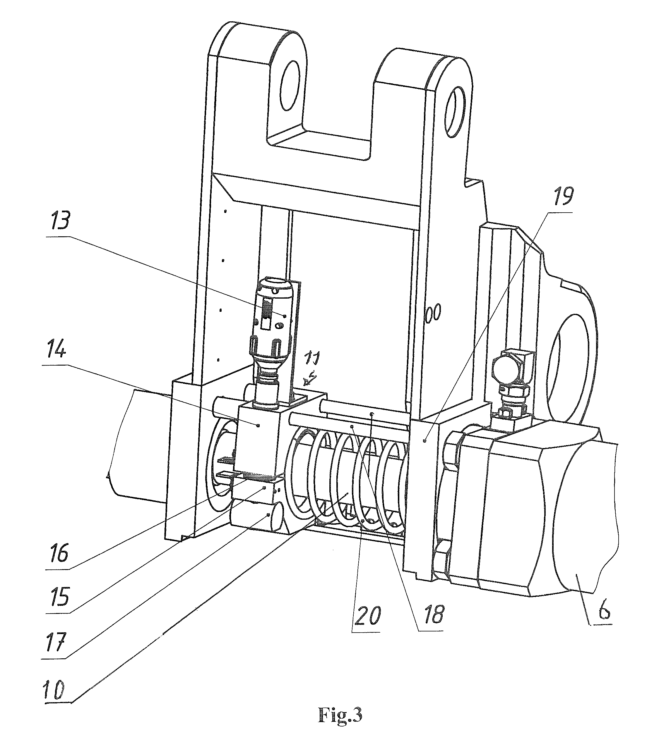
[0018]A machine for rail flash-butt welding comprises two tong-type clamping devices 1 and 2 (FIG. 1), each consisting of two double-arm levers 3 and 4 (FIGS. 1 and 2) mounted on a common central axle 5 (FIGS. 1 and 2) with capability of relative movement along it by displacement-upsetting hydraulic cylinders 6 (FIGS. 1 and 3) operating synchronously from a common hydraulic line. The tong-type clamps 1 and 2 are isolated from each other on all three rods incorporating them and each of the double-arm levers 3 and 4 in the upper part is hinged to the rod or casing of hydraulic cylinders of clamping 7 (FIG. 2), and in the lower part it has the current-carrying clamping jaws 8 (FIG. 2), which clamp the rails to be welded in the web and are manufactured to fit the web profile of the rails being welded. In the right clamping device 2 two welding transformers 9 are arranged (FIG. 2), which are connected in parallel. Welding current to the clamping jaws 8 of the right clamp is supplied by r...


PUM

PropertyMeasurementUnit
displacementaaaaaaaaaa
axial displacementaaaaaaaaaa
welding currentaaaaaaaaaa

Abstract

A machine for the flash butt welding of rails is provided. The machine comprises electric contacts yokes having controlled drives and further comprise holes through which guide pins are passed.

Description

PRIORITY[0001]The present application claims priority to Ukraine Patent Application No. 2011 08577 which was filed on Jul. 8, 2011.TECHNICAL FIELD[0002]This invention pertains to the field of welding, namely to the equipment for the flash-butt welding of rails, and can be used both in welding of separate rails and also in welding of long rail sections with a preliminary tension, as well as in repair of rail tracks under field conditions, and is designed for current supply through the displacement and upsetting rods, electric contacts-yokes with a′ controlled drive and flexible current-carrying jumpers to the clamping jaws of the welding machine and rails being welded.BACKGROUND ART[0003]Known is the machine for flash-butt (Author's Certificate, USSR, No. 201561 of 09.1967, B18, cl. 21h,29), comprising two tong-type clamps which are set into motion by clamping hydraulic cylinders. The tong-type clamps are mounted on a common axle. The right clamp can only rotate around its own axis, ...

Claims


Application Information

Patent Timeline
Patent Type & Authority Patents(United States)
IPC IPC(8): B23K11/04
CPCB23K2201/26B23K11/046E01B29/42B23K2101/26
Inventor KUCHUK-YATSENKO, SERGEY I.KRIVENKO, VALERII G.DIDKOVSKIY, OLEKSANDR V.KHARCHENKO, OLEKSANDR K.LEVCHUK, ANDREY N.
Owner PATON INST OF ELECTRIC WELDING OF THE NAS OF UKRAINE
Why Eureka
Try Eureka