Optical observation device for target acquisition and navigation

a technology of optical observation and target acquisition, applied in the direction of distance measurement, navigation instruments, instruments, etc., to achieve the effect of annoying users, increasing user comfort, and regulating the brightness of the display screen

Active Publication Date: 2014-12-09
LEICA GEOSYSTEMS AG
View PDF32 Cites 13 Cited by
  • Summary
  • Abstract
  • Description
  • Claims
  • Application Information

AI Technical Summary

Benefits of technology

[0010]The invention is therefore based on improving the prior art, making handling easier, and in particular improving the suitability for the hunting field through a navigation function.
[0026]In particular through the provision of a navigation function, using an observation device according to aspects of the invention in the hunting field, finding the game, or the position of the game at the moment of the shot discharge (called the shot point), is made possible in a particularly advantageous manner. Specifically, the game is often still located so it is well visible before the shot discharge, e.g., in a field at a position which can be measured using the observation device, while it is proverbially swallowed by the vegetation after the kill. Also if the game still flees after the shot, the location coordinates of the shot point are of great significance, since a search or check originates from this position while using tracks and finding this position is of great significance in hunting practice. In particular in darkness or during twilight, finding the shot point is made more difficult and is made possible by the illuminated display of the navigation module. The hunter will not be blinded by an unintentionally lighted external display screen due to the automatic shutdown of the illumination of the external display screen during the measurement or subsequent discharge of the shot.

Problems solved by technology

Finding a previously observed destination is not possible using this device, the user must note measured data and results to be able to use them later.

Method used


Image

  • Optical observation device for target acquisition and navigation
  • Optical observation device for target acquisition and navigation
  • Optical observation device for target acquisition and navigation

Examples


Embodiment Construction

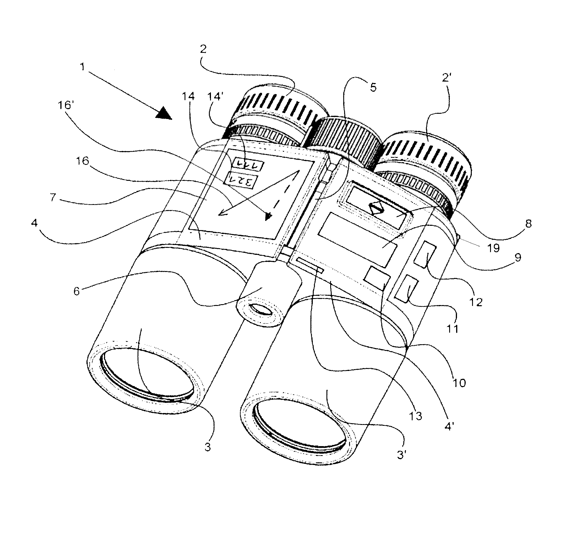
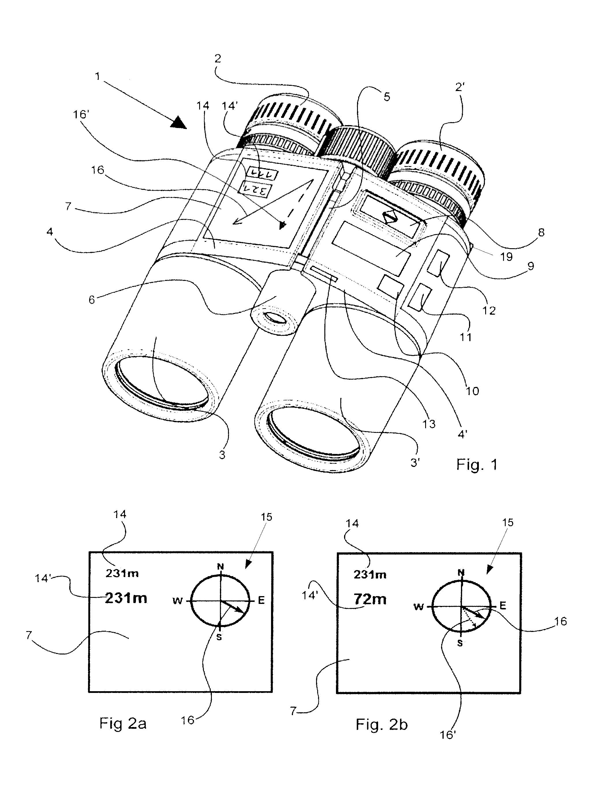
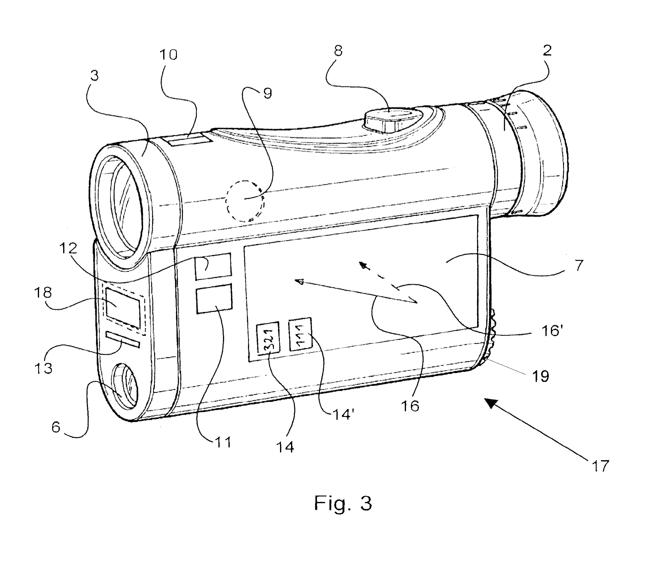
[0035]The field glasses 1 have oculars 2, 2′, objectives 3, 3′, a right housing half 4, and a left housing half 4′. The housing halves 4, 4′ are connected via a joint axis 5 for the eye width adjustment. A laser transmitter 6 is arranged between the objectives 3, 3′ in extension of the joint axis 5. A display screen 7 is provided externally on the housing half 4 as a component of a navigation module (not shown in greater detail). A first switch 8 and, spaced apart therefrom, a second switch 9 are arranged close to the ocular 2′, for a favorable grip, in the housing half 4′. An inclination sensor 10, compass sensor 11, and GPS receiver 12 are schematically shown. A shaft 13 to accommodate a memory card is provided in the region between objective 3′ and laser transmitter 6.

[0036]FIG. 2a schematically shows a display screen 7 at the beginning of navigation. In the upper left region in the illustration, a numeric display 14 having an initial distance to a measured destination is arrange...


PUM


Abstract

An optical observation device for target acquisition and navigation having at least one objective, which is to be turned toward the object to be observed, and at least one ocular, which is to be turned toward the eye of the observer, in a housing, wherein the housing has at least one image reversal system, means for range finding, for location / position determination, for determination of the compass direction, and for displaying data, is distinguished in that an integrated target acquisition module having optoelectronic rangefinder, a GPS position determination, an electronic compass direction determination, and a microcomputer unit for calculating and storing distance and location coordinates of a targeted destination, an integrated navigation module having a display screen, which is arranged externally on the housing, and actuating elements, which are arranged on the housing, for activating functions of the target acquisition and navigation module are provided.

Description

CROSS-REFERENCE TO RELATED PATENT APPLICATIONS[0001]The right of foreign priority is claimed under 35 U.S.C. §119(a) based on Federal Republic of Germany Application No. 10 2012 003 124.6, filed Feb. 16, 2012, the entire contents of which, including the specification, drawings, claims and abstract, are incorporated herein by reference.BACKGROUND OF THE INVENTION[0002]The invention relates to an optical observation device for target acquisition and navigation and a method for target acquisition and navigation.SUMMARY OF THE INVENTION[0003]Manifold optical observation devices, e.g., monocular and binocular field glasses, telescopes, and also telescopic sights with integrated range finding are known. Using these devices, while simultaneously observing an object, precise range finding thereto is possible. So-called laser rangefinder field glasses offer the possibility of binocular observation, while simultaneously displaying a destination and a measured distance by reflecting a display ...

Claims


Application Information

Patent Timeline
Patent Type & Authority Patents(United States)
IPC IPC(8): G01S5/02G01C3/04G01C21/00G02B23/18G02B23/10G01S17/02G01S17/86
CPCG02B23/18G01C21/00G01S17/023G01S5/0284G02B23/10G01C3/04G01S17/86
Inventor DENK, ROBERT
Owner LEICA GEOSYSTEMS AG
Why Eureka
Try Eureka