Rotating field sensor

a sensor and rotating field technology, applied in the direction of electrical/magnetically converting the output of the sensor, instruments, galvano-magnetic devices, etc., can solve the problems of difficult sensor design, distortion of output signal waveforms, and angle detection errors of rotating field sensors, so as to reduce the error in the detected angle

Active Publication Date: 2014-12-09
TDK CORPARATION
View PDF9 Cites 7 Cited by
  • Summary
  • Abstract
  • Description
  • Claims
  • Application Information

AI Technical Summary

Benefits of technology

[0010]It is an object of the present invention to provide a rotating field sensor for detecting an angle that the direction of a rotating magnetic field forms with respect to a reference direction, the rotating field sensor being capable of reducing the error in the detected angle.
[0015]In the rotating field sensor of the present invention, the output signals of the first to fourth detection circuits may each include an error component with a period of ⅓ the signal period that is caused by the magnetic detection elements. According to the rotating field sensor of the present invention, the first arithmetic circuit generates a first signal, and the second arithmetic circuit generates a second signal. The first signal includes a reduced error component with a period of ⅓ the signal period, as compared with the output signals of the first and third detection circuits. The second signal includes a reduced error component with a period of ⅓ the signal period, as compared with the output signals of the second and fourth detection circuits. Based on the first and second signals, the third arithmetic circuit calculates a detected angle value having a correspondence relationship with the angle that the direction of the rotating magnetic field in the reference position forms with respect to the reference direction. Consequently, according to the present invention, it is possible to reduce the error caused by the magnetic detection elements in the angle detected by the rotating field sensor. As used herein, the phrase “reduced error component” means that the ratio of the amplitude of the error component to the amplitude of the signal is reduced.
[0016]Preferably, in the rotating field sensor of the present invention, the output signal of the second detection circuit differs from the output signal of the first detection circuit in phase by an odd number of times ¼ the signal period. Preferably, the output signal of the third detection circuit differs from the output signal of the first detection circuit in phase by an integer multiple of ⅙ the signal period other than an integer multiple of ½ the signal period. Also preferably, the output signal of the fourth detection circuit differs from the output signal of the third detection circuit in phase by an odd number of times ¼ the signal period. The aforementioned preferable configuration makes it possible that, when the first arithmetic circuit generates the first signal based on the output signals of the first and third detection circuits, the error components included in the respective output signals of the first and third detection circuits cancel each other out. As a result of the aforementioned preferable configuration, the output signal of the second detection circuit and the output signal of the fourth detection circuit differ in phase by an integer multiple of ⅙ the signal period (other than an integer multiple of ½ the signal period). This makes it possible that, when the second arithmetic circuit generates the second signal based on the output signals of the second and fourth detection circuits, the error components included in the respective output signals of the second and fourth detection circuits cancel each other out. Consequently, the aforementioned preferable configuration allows more effective reduction of the error caused by the magnetic detection elements in the angle detected by the rotating field sensor.
[0025]According to the rotating field sensor of the present invention, there are generated a first signal and a second signal. The first signal includes a reduced error component with a period of ⅓ the signal period, as compared with the output signals of the first and third detection circuits. The second signal includes a reduced error component with a period of ⅓ the signal period, as compared with the output signals of the second and fourth detection circuits. A detected angle value having a correspondence relationship with the angle that the direction of the rotating magnetic field in the reference position forms with respect to the reference direction is calculated based on the first and second signals. Consequently, according to the present invention, it is possible to reduce the error in the angle detected by the rotating field sensor.

Problems solved by technology

If the waveforms of the output signals of the MR elements are distorted, the angle detected by the rotating field sensor may include some error.
One of the causes of the distortion of the output signal waveforms of the MR elements is the MR elements themselves.
This poses a problem that the design of the sensor is not easy.
As has been described, a rotating field sensor that uses MR elements as the magnetic detection elements has the problem that the angle detected by the rotating field sensor may include some error.
However, this problem can occur in any rotating field sensor that includes magnetic detection elements to detect the angle that the direction of a rotating magnetic field forms with respect to a reference direction.

Method used


Image

  • Rotating field sensor
  • Rotating field sensor
  • Rotating field sensor

Examples


first embodiment

[First Embodiment]

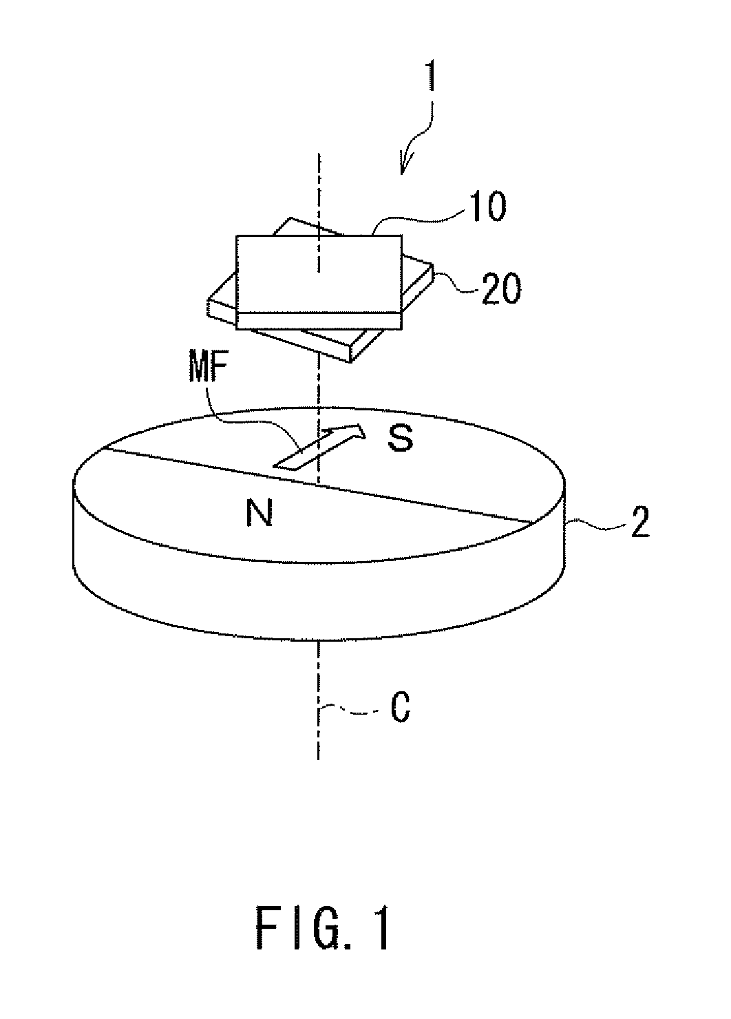
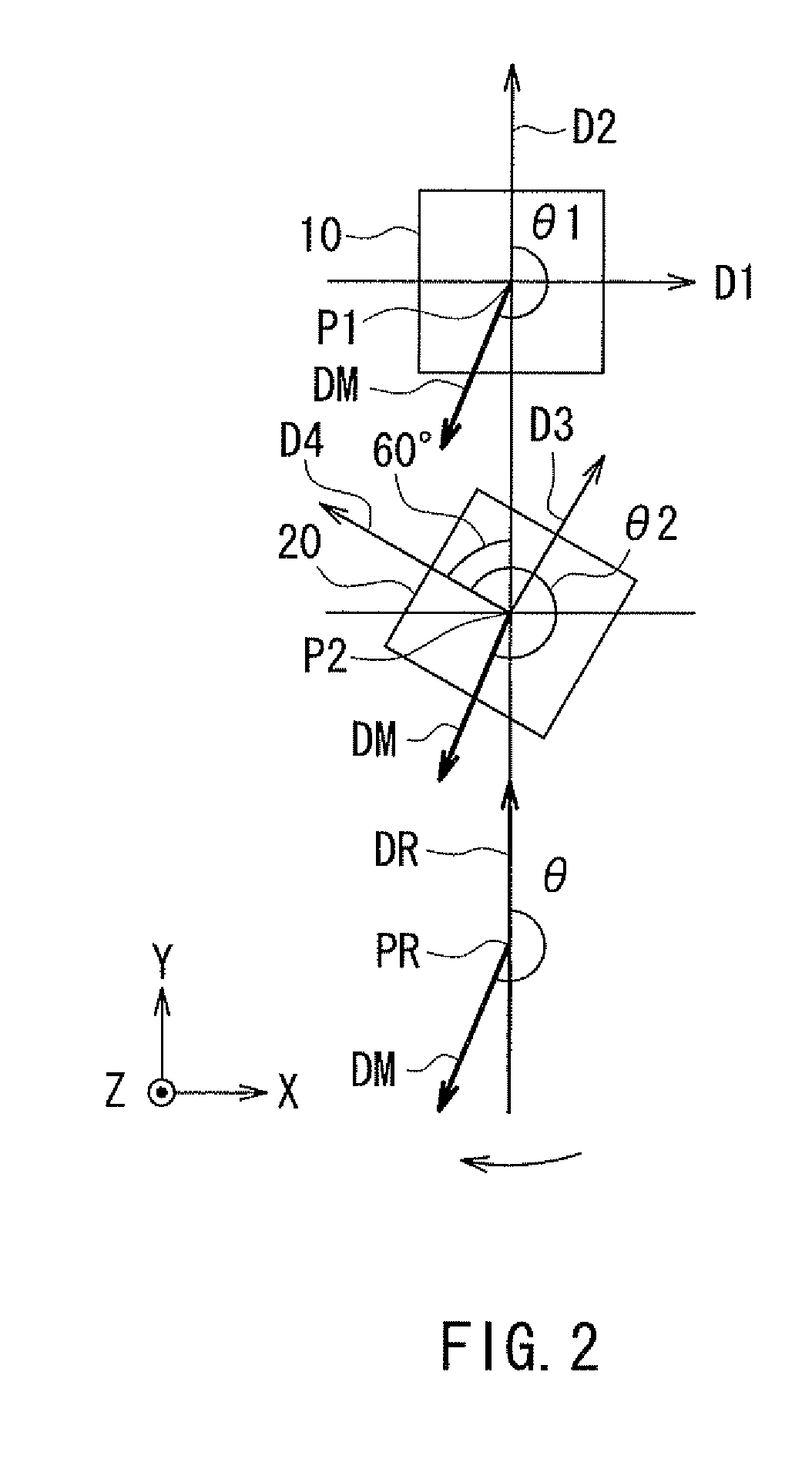
[0058]Preferred embodiments of the present invention will now be described in detail with reference to the drawings. First, reference is made to FIG. 1 and FIG. 2 to describe the general configuration of a rotating field sensor according to a first embodiment of the invention. FIG. 1 is a perspective view showing the general configuration of the rotating field sensor according to the present embodiment. FIG. 2 is an explanatory diagram illustrating the definitions of directions and angles in the present embodiment.

[0059]As shown in FIG. 1, the rotating field sensor 1 according to the present embodiment detects the angle that the direction of a rotating magnetic field MF in a reference position forms with respect to a reference direction. In FIG. 1, a cylindrical magnet 2 is shown as an example of means for generating the rotating magnetic field MF whose direction rotates. The magnet 2 has an N pole and an S pole that are arranged symmetrically with respect to a vir...

second embodiment

[Second Embodiment]

[0156]A rotating field sensor according to a second embodiment of the invention will now be described with reference to FIG. 19. FIG. 19 is an explanatory diagram showing the configuration of the rotating field sensor according to the present embodiment. In FIG. 19, a magnet 102 including one or more pairs of N and S poles alternately arranged in a ring shape is shown as an example of the means for generating a rotating magnetic field whose direction rotates. In the example shown in FIG. 19, the magnet 102 includes two pairs of N and S poles. The rotating field sensor 1 according to the present embodiment detects the direction of the rotating magnetic field generated from the outer periphery of the magnet 102. In the example shown in FIG. 19, the plane of the drawing of FIG. 19 is an XY plane, and the direction perpendicular to the plane is the Z direction. The N and S poles of the magnet 102 are arranged symmetrically with respect to the center of rotation parall...

modification examples

[Modification Examples]

[0159]Reference is now made to FIG. 20 to FIG. 22 to describe first to third modification examples of the present embodiment. The first modification example will be described first, with reference to FIG. 20. FIG. 20 is an explanatory diagram showing the configuration of a rotating field sensor of the first modification example of the present embodiment. The configuration of the rotating field sensor 1 of the first modification example is basically the same as that of the rotating field sensor shown in FIG. 19. In the example shown in FIG. 20, the first direction D1 and the third direction D3 differ from each other by 60° in the direction of rotation of the rotating magnetic field, and are both tilted with respect to the radial direction of the magnet 102 in the XY plane. Preferably, the angles that the first direction D1 and the third direction D3 form with respect to the radial direction of the magnet 102 are equal in absolute value, and more specifically, 3...


PUM


Abstract

A first detection unit has first and second detection circuits. A second detection unit has third and fourth detection circuits. Output signals of the second and fourth detection circuits differ from output signals of the first and third detection circuits in phase, respectively, by an odd number of times ¼ the signal period. The output signal of the third detection circuit differs from the output signal of the first detection circuit in phase by an integer multiple of ⅙ the signal period other than an integer multiple of ½ the signal period. A rotating field sensor generates a first signal based on the output signals of the first and third detection circuits, generates a second signal based on the output signals of the second and fourth detection circuits, and calculates a detected angle value based on the first and second signals.

Description

BACKGROUND OF THE INVENTION[0001]1. Field of the Invention[0002]The present invention relates to a rotating field sensor for detecting an angle that the direction of a rotating magnetic field forms with respect to a reference direction.[0003]2. Description of the Related Art[0004]In recent years, rotating field sensors have been widely used to detect the rotational position of an object in various applications such as detecting the rotational position of an automotive steering wheel. Rotating field sensors are used not only to detect the rotational position of an object but also to detect a linear displacement of an object. Systems using rotating field sensors are typically provided with means (for example, a magnet) for generating a rotating magnetic field whose direction rotates in conjunction with the rotation or linear movement of the object. The rotating field sensors use magnetic detection elements to detect the angle that the direction of the rotating magnetic field forms wit...

Claims


Application Information

Patent Timeline
Patent Type & Authority Patents(United States)
IPC IPC(8): B82Y25/00G01R33/09G06F19/00G01D5/14
CPCB82Y25/00G01D5/145G01R33/093
Inventor SARUKI, SHUNJIHIRABAYASHI, HIRAKUKOMASAKI, YOSUKE
Owner TDK CORPARATION
Why Eureka
Try Eureka