Service hole cover mounting structure, and vehicular battery mounting structure provided therewith

a technology for mounting structures and vehicular batteries, which is applied in the direction of electric propulsion mounting, roofs, transportation and packaging, etc., can solve the problems of tilting of the boot member, and achieve the effect of improving the durability of the battery unit and facilitating deformation

Active Publication Date: 2014-12-16
TOYOTA JIDOSHA KK
View PDF7 Cites 12 Cited by
  • Summary
  • Abstract
  • Description
  • Claims
  • Application Information

AI Technical Summary

Benefits of technology

[0011]According to the structure described above, the bent-back portion is bent back from the lower end portion of the housing recessed portion toward the vehicle floor side via the extended portion that extends toward the outside of the housing recessed portion, and the first seal member is provided in the gap between this extended portion and the battery unit. This first seal member is provided along the extended portion, and fills in the gap between the extended portion and the battery unit. As a result, rainwater and dust and the like are inhibited from entering the housing recessed portion. Therefore, the durability of the battery unit improves.
[0012]Also, when the service hole cover is attached to the vehicle floor, the extended portion is supported by the battery unit via the first seal member. As a result, horizontal displacement of the extended member with respect to the battery unit is inhibited. Therefore, when the bent-back portion is pressed toward the operating portion of the battery unit by the vehicle floor, the bent-back portion will more easily deform toward the housing recessed portion side with the extended portion as the fulcrum. Therefore, contact between the housing recessed portion and the operating portion of the battery unit is able to be inhibited.
[0018]According to the battery mounting structure described above, contact between the housing recessed portion of the service hole cover and the operating portion of the battery unit when a vehicle collision occurs is able to be inhibited by providing the service hole cover mounting structure described above. Therefore, the durability of the battery unit is able to be improved.
[0020]According to the battery mounting structure described above, during maintenance of the battery unit, the electrical circuit of the battery module is able to be electrically interrupted by removing the service hole cover from the vehicle floor and operating the operating member of the operating portion of the battery unit through the service hole. Therefore, the ability to perform maintenance on the battery unit improves.

Problems solved by technology

However, with the technology described in JP 2009-083601 A, if the floor panel is displaced horizontally with respect to the battery unit when a vehicle collision occurs, the boot member may become tilted with respect to the operating lever, and the boot member may contact the operating lever.

Method used


Image

  • Service hole cover mounting structure, and vehicular battery mounting structure provided therewith
  • Service hole cover mounting structure, and vehicular battery mounting structure provided therewith
  • Service hole cover mounting structure, and vehicular battery mounting structure provided therewith

Examples


Embodiment Construction

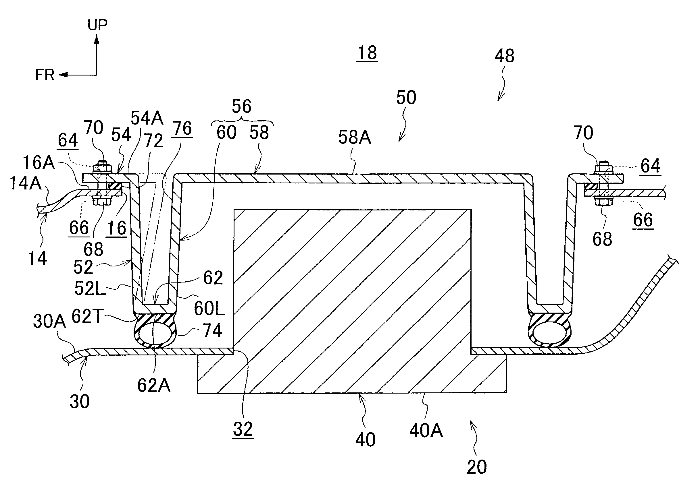
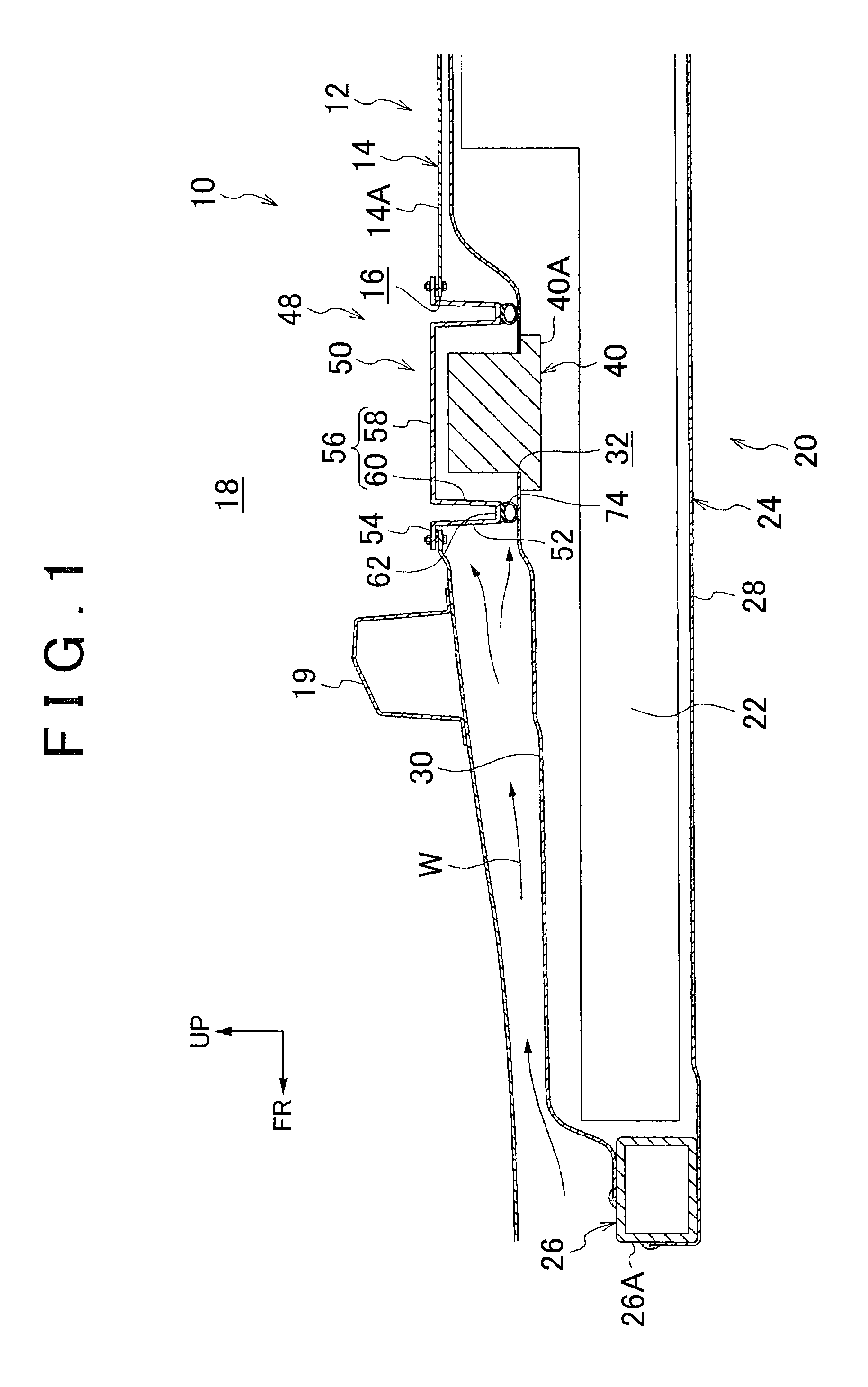
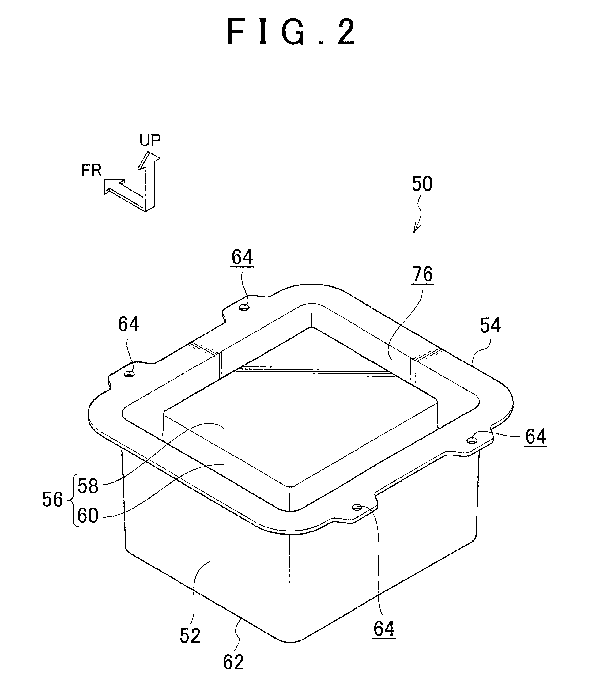
[0027]Hereinafter, example embodiments of the invention will be described with reference to the accompanying drawings. In the drawings, the arrow FR indicates the forward direction in a vehicle longitudinal direction, and the arrow UP indicates the upward direction in a vehicle vertical direction.

[0028]FIG. 1 is a longitudinal sectional view, as viewed from the outside in a vehicle width direction (i.e., the left side of the vehicle body), of a lower portion of a vehicle 12 to which a vehicular battery mounting structure 10 according to one example embodiment has been applied. This vehicle 12 may be, for example, an electric vehicle, a gasoline hybrid vehicle, or a fuel cell hybrid vehicle or the like, that runs using an electric motor, not shown, as a drive source. A battery unit 20 that stores electric power to be supplied to the electric motor is mounted below, in the vehicle vertical direction, a floor panel 14 that serves as the vehicle floor.

[0029]As shown in FIG. 1, the batte...


PUM


Abstract

A service hole cover has a housing recessed portion that has been brought from above the vehicle floor toward the battery unit through the service hole through a service hole formed in a floor panel from inside a vehicle cabin, and that covers an upper portion of a power supply circuit interrupting device from the floor panel side. An extended portion that extends toward an outside of the housing recessed portion is provided on a lower end portion of an inner peripheral wall portion of this housing recessed portion. Also, a bent-back portion that is bent back toward the floor panel side is provided on an outer peripheral side end portion of the extended portion. This bent-back portion will easily deform toward the inner peripheral wall portion side of the housing recessed portion with the outer peripheral side end portion of the extended portion as the fulcrum.

Description

INCORPORATION BY REFERENCE[0001]The disclosure of Japanese Patent Application No. 2011-255321 filed on Nov. 22, 2011 including the specification, drawings and abstract is incorporated herein by reference in its entirety.BACKGROUND OF THE INVENTION[0002]1. Field of the Invention[0003]The invention relates to a service hole cover mounting structure, and a vehicular battery mounting structure provided with this service hole cover mounting structure.[0004]2. Description of the Related Art[0005]Japanese Patent Application Publication No. 2009-083601 (JP 2009-083601 A), for example, describes an electric vehicle in which a battery unit having a service plug is mounted under a floor panel. The electric vehicle described in JP 2009-083601 A includes a boot member that is arranged between a boot mounting hole formed in the floor panel and a service plug opening formed in an upper surface of the battery unit, and a cap member that covers the boot mounting hole. The boot member is made of synt...

Claims


Application Information

Patent Timeline
Patent Type & Authority Patents(United States)
IPC IPC(8): B60K1/04
CPCB60K2001/0438B60K1/04
Inventor SAEKI, KOJI
Owner TOYOTA JIDOSHA KK
Why Eureka
Try Eureka