
Firearm suppressor

a technology of suppressors and firearms, applied in the direction of weapons, weapon components, etc., can solve the problems of receiving hostile fire, affecting the accuracy of fire, and deafening the shooter and others nearby, so as to reduce the sound level, prevent any loss of accuracy, and attenuate the sound waves

Active Publication Date: 2014-12-16
MCKENZIE THOMAS
View PDF17 Cites 21 Cited by
  • Summary
  • Abstract
  • Description
  • Claims
  • Application Information

AI Technical Summary

Benefits of technology

The invention is a firearm suppressor that reduces sound levels by using a minimum of three tapered baffles with interior angles between 15.3 and 26.2 degrees, and preferably about 21.3 degrees. The baffles have overlapping surfaces that create an acoustical dampening effect, reducing sound waves in the human hearing range. The design also includes pressed together overlapping tapered surfaces between consecutive baffles, which eliminates welds and distortions. The suppressor is made of titanium to reduce weight and has a quick disconnect mount to prevent carbon buildup. The technical effects of the invention include reduced sound levels, improved hearing protection, and improved performance in automatic fire.

Problems solved by technology

Firearms are often used in situations where the very loud sounds resulting from firing the weapons may both give away the position of the shooter or, especially indoors, temporarily deafen the shooter and others nearby.
In a combat situation, giving away a shooters position may result in receiving hostile fire.
Many known suppressors are available, but suffer from various deficiencies.
Many do not reduce sound levels sufficiently.
The lead softens quickly with temperature and melts at 621 degrees Fahrenheit which is a problem in known suppressors made of stainless steel and other materials which hold the heat inside the suppressor creating an oven like environment for the bullets to pass through.
This high temperature causes the lead to deform resulting in destabilizing the bullets as they pass through the suppressor causing baffle strikes and catastrophic failures.

Method used


Image

  • Firearm suppressor
  • Firearm suppressor
  • Firearm suppressor

Examples


Embodiment Construction

[0062]The following description is of the best mode presently contemplated for carrying out the invention. This description is not to be taken in a limiting sense, but is made merely for the purpose of describing one or more preferred embodiments of the invention. The scope of the invention should be determined with reference to the claims.

[0063]In the following description, forward is in the direction of fire of the rifle and rearward is towards the rifle butt.

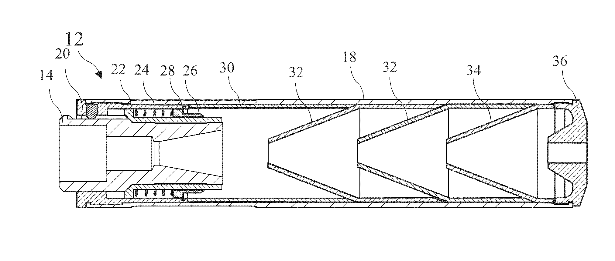
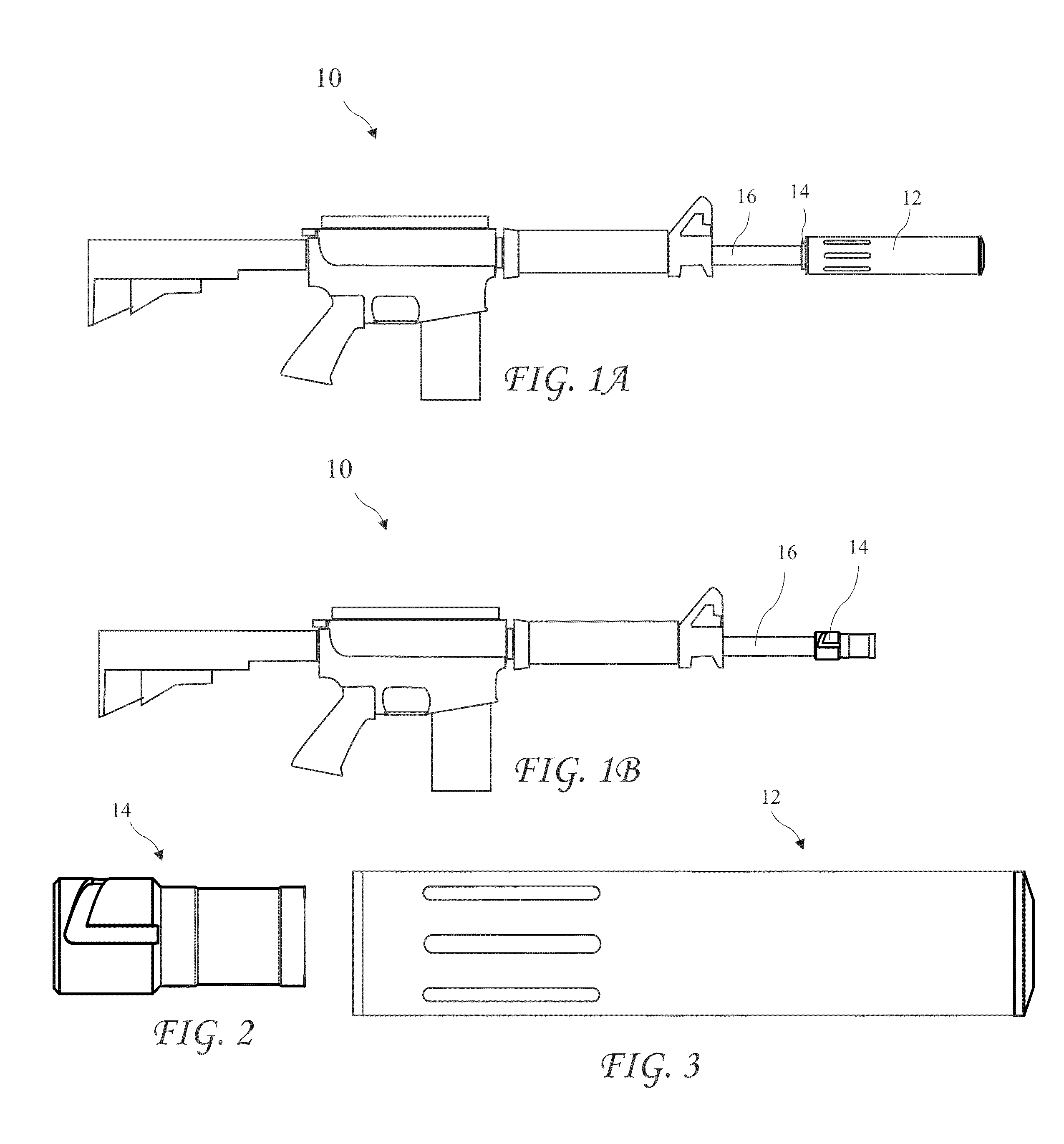
[0064]A side view of a rifle 10 and suppressor 12 according to the present invention is shown in FIG. 1, a side view of the rifle 10 with the suppressor 12 removed and showing a muzzle adapter 14 for the suppressor 12 is shown in FIG. 1B, a side view of the muzzle adapter 14 alone is shown in FIG. 2, and a side view of the suppressor 12 alone is shown in FIG. 3. The suppressor 12 is attached to the muzzle adapter 14 by a quick disconnect mount 14.

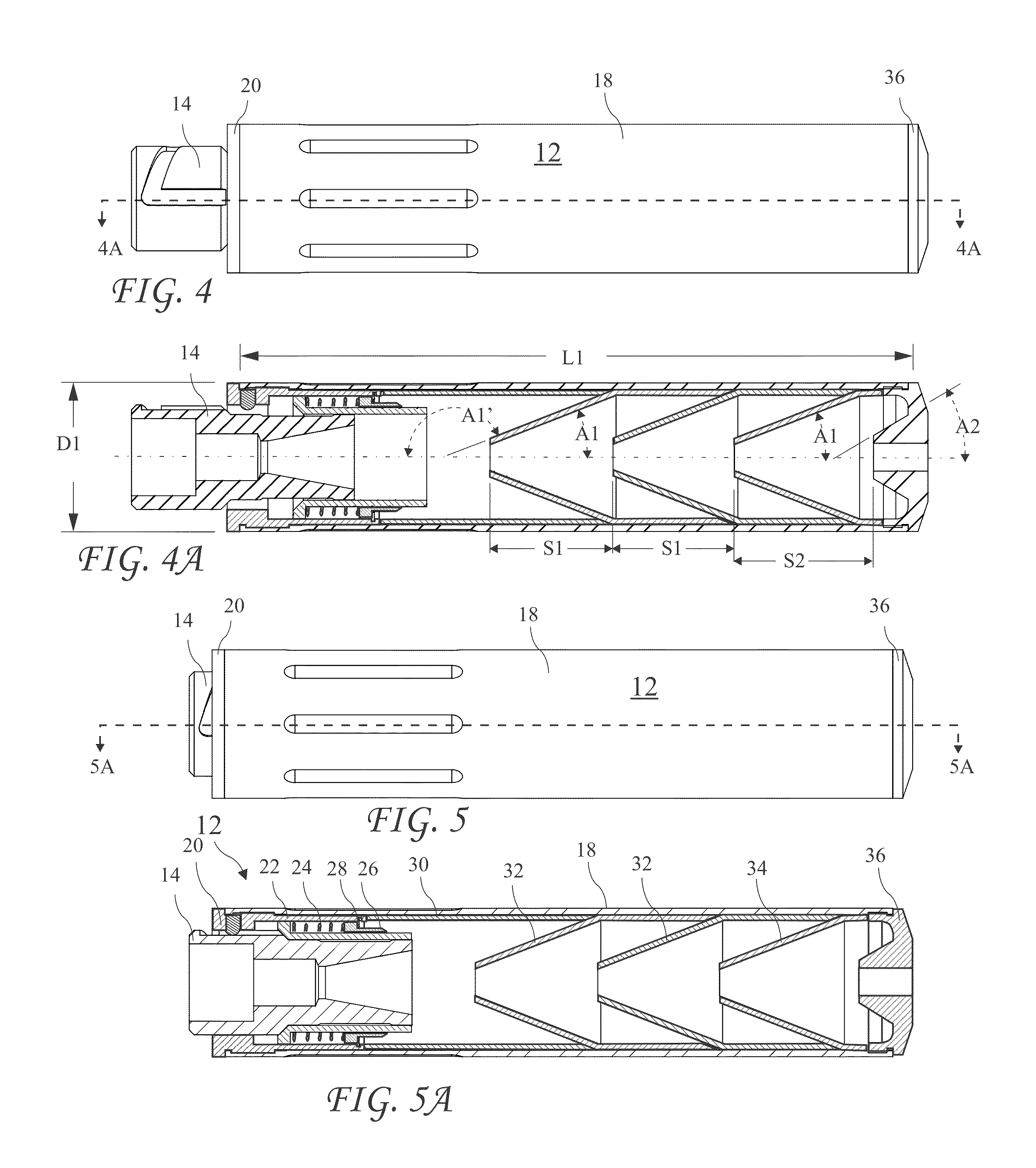
[0065]A detailed side view of the suppressor 12 partially attached to the muzzle...


PUM


Abstract

A suppressor includes baffles with geometry and spacing minimizing sound level in the human hearing range, and overlapping tapers on consecutive elements replacing welds. The geometry includes conical baffles with approach angles between 153.7 and 163.7 degrees and at least one inch separation. The suppressor is assembled by compressing the elements between threaded end caps, thus expending the overlapping tappers against the interior of a suppressor tube to center and align the baffles. The suppressor may be attached to a rifle using a quick disconnect mount which includes an adapter fixed to the rifle barrel and having an “L” shaped slot with a first leg parallel to the barrel and a second leg turned greater than 90 degrees towards the front of the adapter. A post in the suppressor engaged the slot and a spring biases the suppressor forward and holds the post at the end of the turned leg.

Description

BACKGROUND OF THE INVENTION[0001]The present invention relates firearm sound suppressors and in particular to a suppressor for automatic weapons.[0002]Firearms are often used in situations where the very loud sounds resulting from firing the weapons may both give away the position of the shooter or, especially indoors, temporarily deafen the shooter and others nearby. In a combat situation, giving away a shooters position may result in receiving hostile fire. Even temporary deafening may prevent communication between team members and prevent the shooter from hearing danger signs.[0003]Many known suppressors are available, but suffer from various deficiencies. Many do not reduce sound levels sufficiently.[0004]When used on automatic weapons, suppressor temperature may build quickly. Bullets are commonly constructed of jacketed lead. The lead softens quickly with temperature and melts at 621 degrees Fahrenheit which is a problem in known suppressors made of stainless steel and other m...

Claims


Application Information

Patent Timeline
Patent Type & Authority Patents(United States)
IPC IPC(8): F41A21/30F41A21/00
CPCF41A21/30
Inventor MCKENZIE, THOMAS
Owner MCKENZIE THOMAS
Learn More