Planar light source device and illumination apparatus

a light source device and illumination apparatus technology, applied in semiconductor devices, lighting and heating apparatus, instruments, etc., can solve the problems of affecting the illumination quality of the illumination area, the inability to obtain uniform illumination light, and the difference in luminance with other illumination areas, so as to prevent the degradation of illumination quality and uniform illumination. , the effect of uniform illumination

Inactive Publication Date: 2014-12-16
OPTO DESIGN INC
View PDF11 Cites 11 Cited by
  • Summary
  • Abstract
  • Description
  • Claims
  • Application Information

AI Technical Summary

Benefits of technology

[0030]The invention provides an edge lighting planar light source device that: does not require a light guide plate essential in related arts even when a point light source with strong directivity is used as a light source; is lightweight and inexpensive; can illuminate both sides or one side, that is, illuminate a wide range on each side in single-sided illumination or double-sided illumination; and can provide high-quality planar illumination light with uniform illuminance. In particular, even when the characteristics vary among a plurality of point light sources, the light blocking region hides the region where the illumination color or illuminance significantly varies, thereby preventing degradation of illumination quality. Furthermore, uncomfortable glare does not occur because light from the point light source is not directly transmitted. In addition, even when a light diffusion plate is disposed above the surface of the optical reflection plate, an image of the point light source is not formed.
[0031]The invention also provides a disk-shaped planar light source device that: does not require a light guide plate essential in related arts even when a point light source with strong directivity is used as a light source; is lightweight and inexpensive; can illuminate a wide range; and can provide high-quality planar illumination light with uniform illuminance. In particular, even when the characteristics vary among a plurality of point light sources, the light blocking region hides the region where the illumination color or illuminance significantly varies, thereby preventing degradation of illumination quality. Furthermore, uncomfortable glare does not occur because light from the point light source is not directly transmitted. In addition, even when a light diffusion plate is disposed above the surface of the optical reflection plate, an image of the point light source is not formed.
[0032]The invention further provides an illumination apparatus that: does not require a light guide plate essential in related art even when a point light source with strong directivity is used as a light source; is lightweight and inexpensive; and can provide large-area, uniform, and high-quality planar illumination light.

Problems solved by technology

However, if this distance is reduced, the light diffusion plate reflects the outer shape of the light source, which makes visibility poor, resulting in degradation of illumination quality.
If a point light source having strong directivity is used as the light source, the luminance becomes extremely high at the light diffusion plate immediately above the point light source, thereby causing a luminance difference with other illumination areas, and as a result, uniform illumination light cannot be obtained.
However, this method causes new problems.
For example, it is difficult to obtain illumination light having a desired illuminance because the whole area becomes darker as the distance increases, and it is impossible to reduce the thickness.
Because of the problems above, it is difficult to adopt direct-type illumination apparatuses in some applications.

Method used


Image

  • Planar light source device and illumination apparatus
  • Planar light source device and illumination apparatus
  • Planar light source device and illumination apparatus

Examples


Embodiment Construction

[0048]Embodiments of the invention will be described below with reference to the drawings. It is noted that the embodiments shown below only illustrate a planar light source device and an illumination apparatus using the planar light source device for embodying the technical idea of the invention and are not intended to limit the invention thereto, and other embodiments that fall within the scope of the claims are also equally applicable.

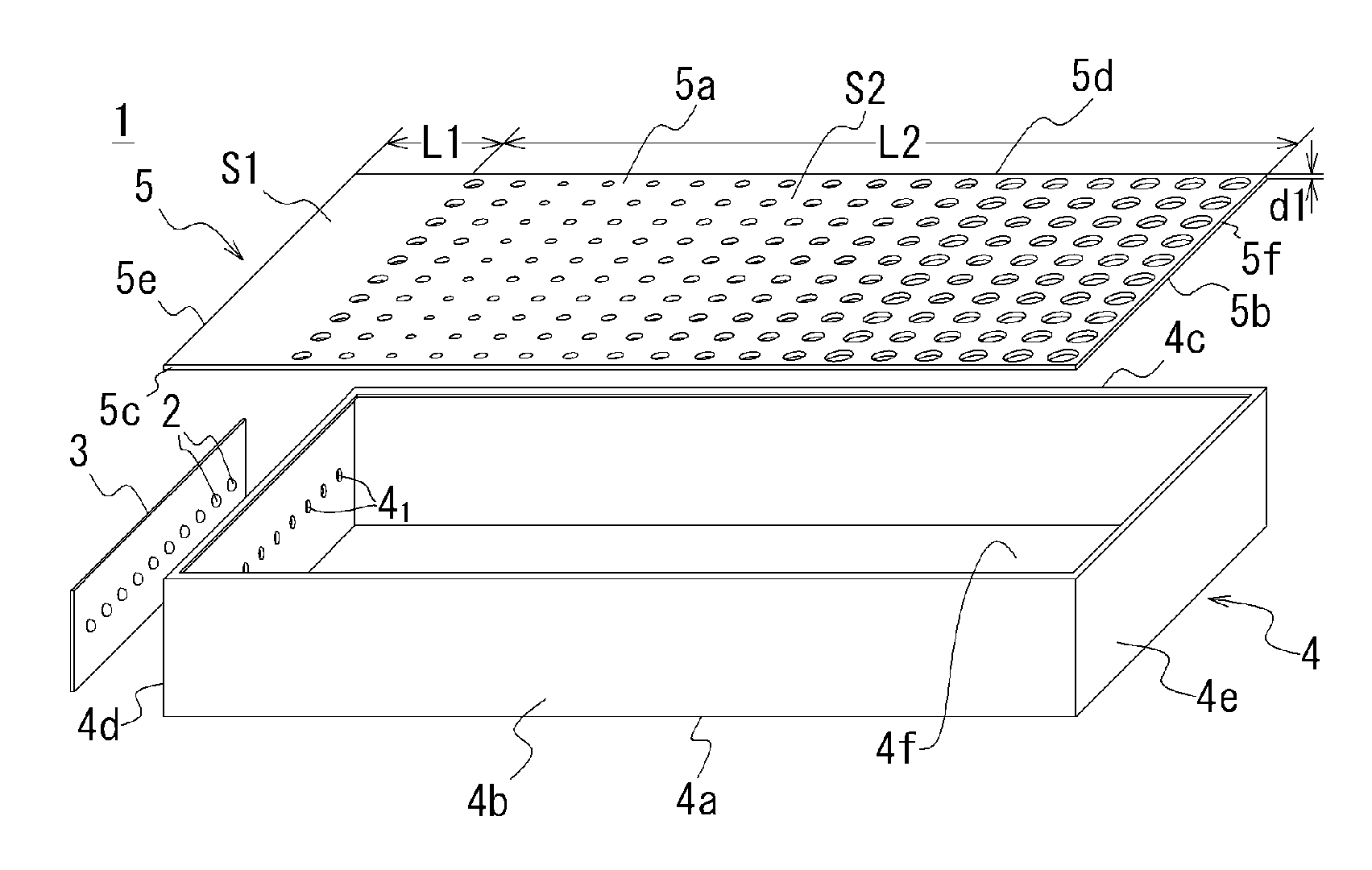
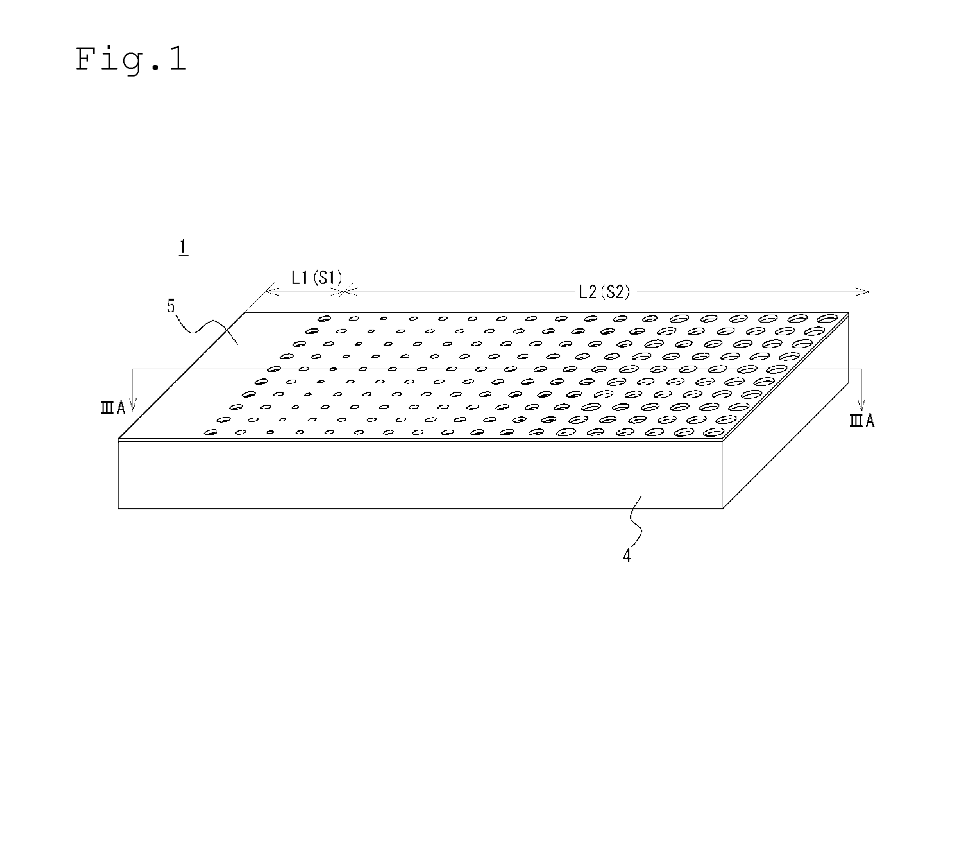
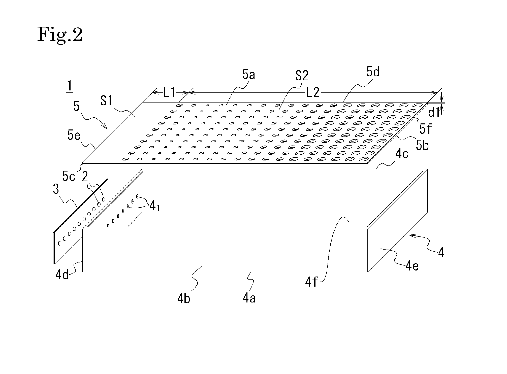
[0049]With reference to FIG. 1 to FIG. 4, a planar light source device according to an embodiment of the invention will be described. FIG. 1 is an external perspective view of a planar light source device according to an embodiment of the invention. FIG. 2 is an exploded perspective view of the planar light source device in FIG. 1. FIG. 3A is a sectional view taken along line IIIA-IIIA in FIG. 1, and FIG. 3B is an enlarged view of a portion IIIB in FIG. 3A. FIG. 4 shows an optical reflection plate included in the planar light source device in FIG. 1...


PUM

PropertyMeasurementUnit
depthaaaaaaaaaa
lengthaaaaaaaaaa
thicknessaaaaaaaaaa

Abstract

To provide a planar light source device that can provide large-area, uniform, and high-quality planar illumination light.A planar light source device includes a main body case 4 that surrounds the periphery of a gap between a pair of optical reflection plates disposed to face each other with side plates, and a plurality of point light sources 2 arranged at predetermined intervals on at least one side plate of the main body case. The planar light source device allows light from the point light sources 2 to be transmitted through at least one of the pair of optical reflection plates 5 and emitted to the outside. At least one 5 of the pair of optical reflection plates 5 includes a light blocking region S1 that blocks light from the point light sources on the point light sources 2 side, and a light transmission region S2 that does not allow the light from the point light sources 2 to be directly transmitted but allows reflection light reflected between the optical reflection plates to be transmitted, and is aligned so that transmissivity increases as the distance from the light blocking region S1 increases, and luminance is substantially uniform on the surface of the optical reflection plate.

Description

RELATED APPLICATIONS[0001]This application is a nationalization under 35 U.S.C. 371 of PCT / JP2011 / 063161, filed Jun. 8, 2011, and published as WO 2011 / 155537 A1 on Dec. 15, 2011, which claims priority to Japanese Patent Application Serial No. 2010-131540, filed Jun. 8, 2010, which applications and publication are incorporated herein by reference in their entirety.TECHNICAL FIELD[0002]The present invention relates to a planar light source device and an illumination apparatus, and more specifically to an edge lighting planar light source device using a point light source having strong directivity as a light source for emitting light from the point light source in the form of planar light, and an illumination apparatus using the planar light source device.BACKGROUND ART[0003]Planar illumination apparatuses are often used, for example, for backlights of liquid crystal panels. In general, planar illumination apparatuses of this type are mainly classified into: direct types in which a lig...

Claims


Application Information

Patent Timeline
Patent Type & Authority Patents(United States)
IPC IPC(8): F21V8/00G02F1/1335F21Y105/00F21Y103/00F21Y101/02F21V7/00F21V7/04F21K99/00F21V11/14
CPCG02F1/133615G02F1/1336F21Y2103/003F21Y2101/02G02B6/0096F21V7/0066G02F1/133606F21Y2105/00F21K9/00F21V11/14G02B6/0061F21Y2103/10F21Y2115/10F21K9/68
Inventor SATO, EIICHIFUKUOKA, KENJISATO, HIROYASUSATO, RIHITO
Owner OPTO DESIGN INC
Why Eureka
Try Eureka