Surface texture measuring apparatus
a technology of surface texture and measuring apparatus, which is applied in the direction of mechanical measurement arrangements, mechanical roughness/irregularity measurements, instruments, etc., can solve the problem of long measurement tim
- Summary
- Abstract
- Description
- Claims
- Application Information
AI Technical Summary
Benefits of technology
Problems solved by technology
Method used
Image
Examples
example-1
Measurement Example-1
FIGS. 5 and 6
[0061]Measurement example-1 is an example in which the inner surface of a hole H of a subject of measurement W1 is measured.
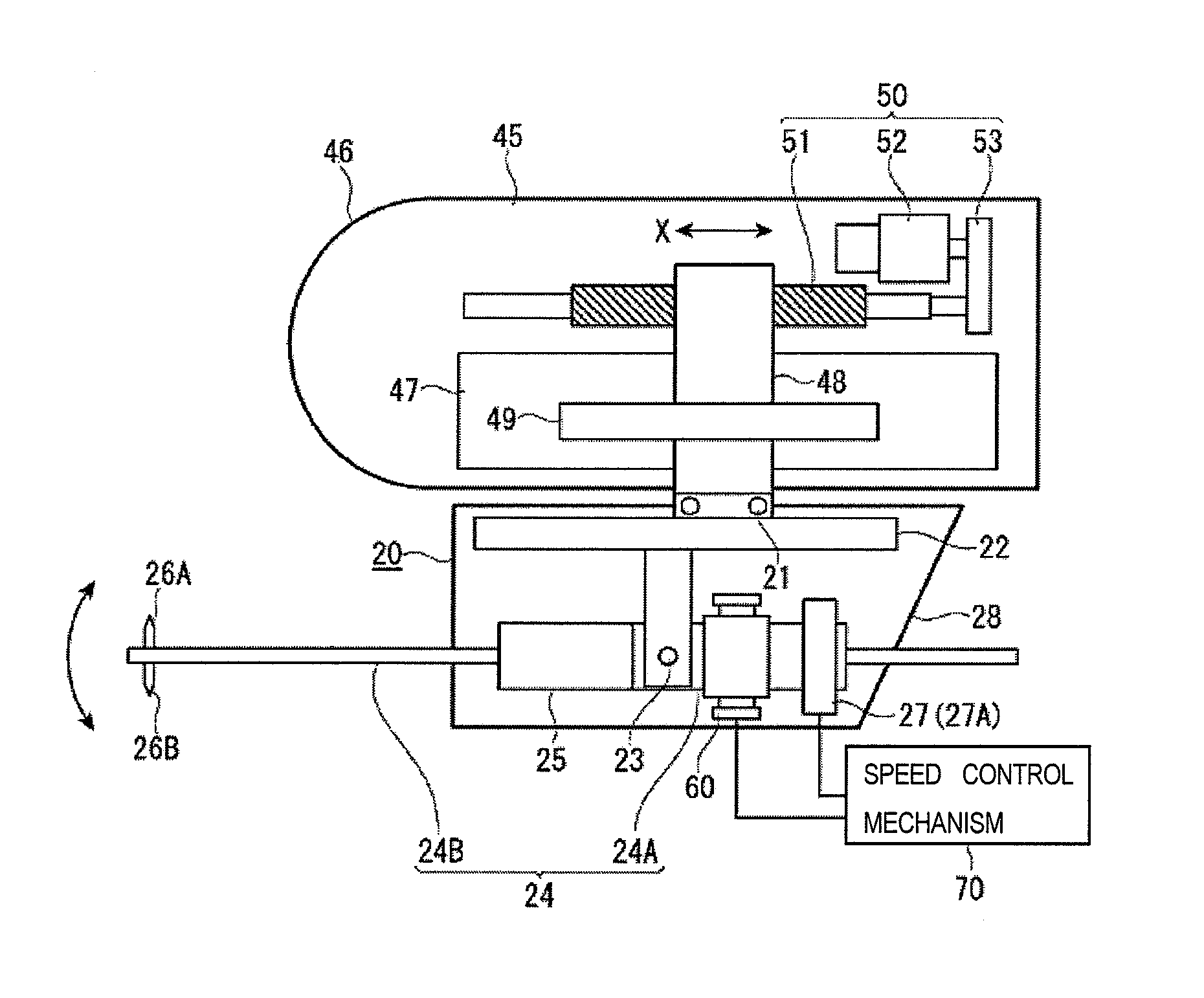
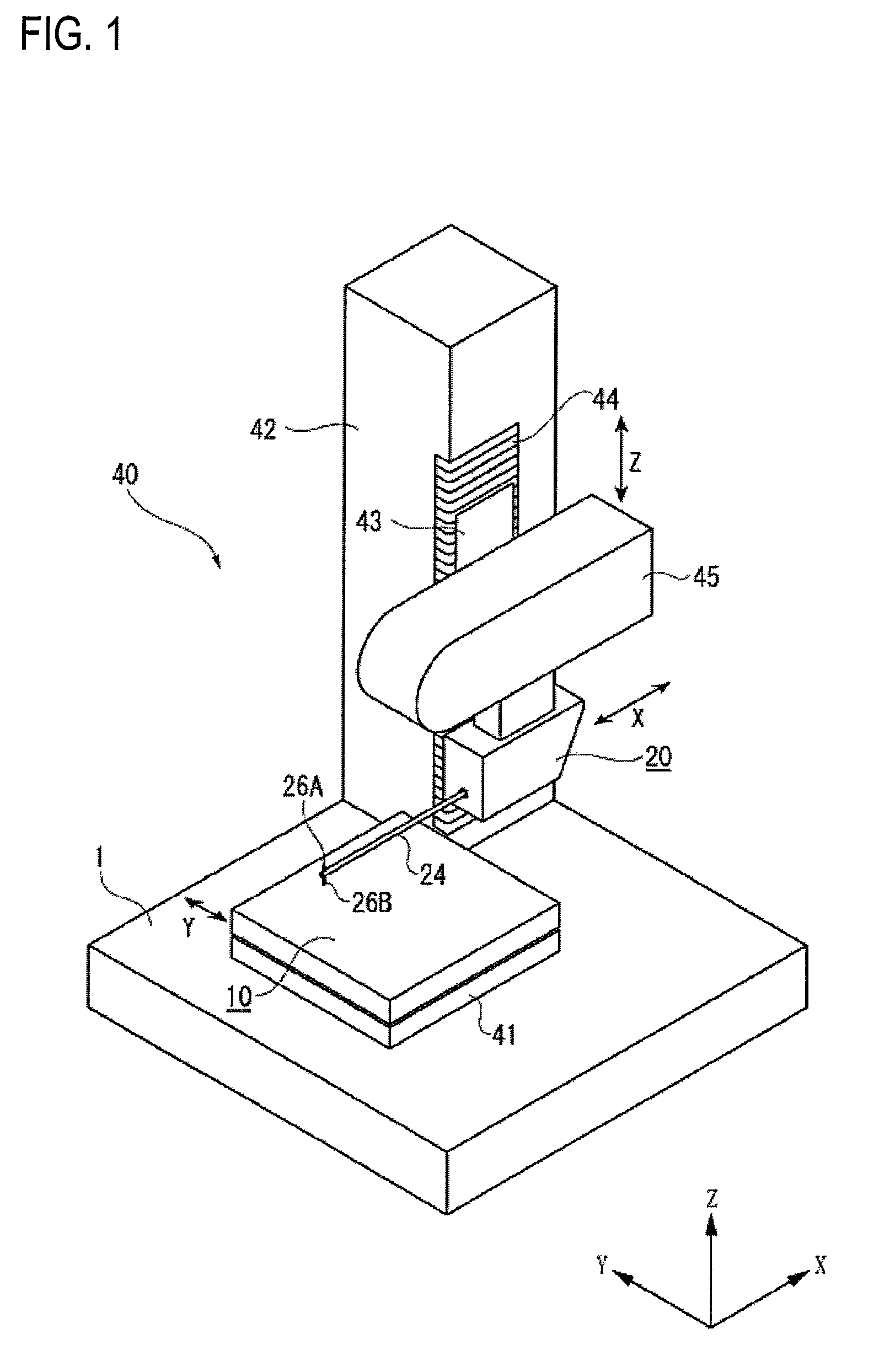
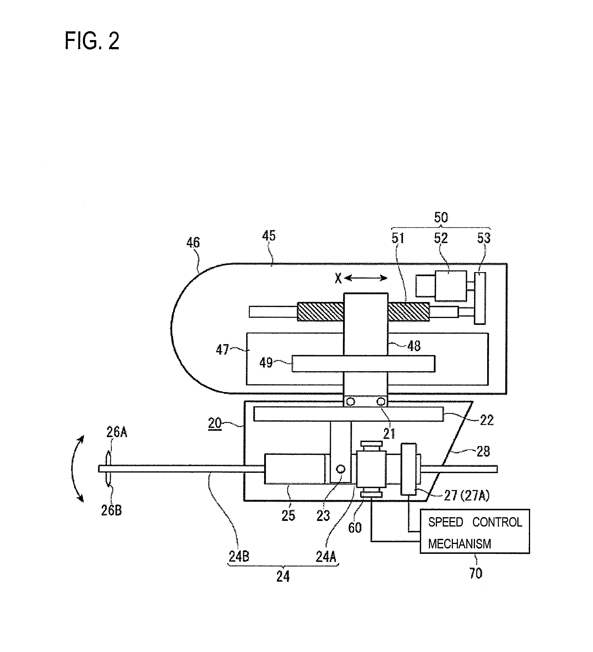
[0062]As shown in FIG. 5, the subject of measurement W1 is placed on the stage 10. Then, the styli 26A and 26B of the measurement arm 24 are placed inside the hole H of the subject of measurement W1 by driving the relative movement mechanism 40. Then, the posture of the measurement arm 24 is switched by the posture switching mechanism 60 so that the tip of the measurement arm 24 is urged downward, for example, whereby the downward stylus 26B is brought into contact with the bottom surface of the hole H (see FIG. 6).
[0063]In this state, as the relative movement mechanism 40 causes a relative movement between the stylus displacement detector 20 and the stage 10 in the axial direction of the hole H (X-axis direction), the detection unit 27 detects swing amounts of the measurement arm 24. A surface texture of the bottom surface of ...
example-2
Measurement Example-2
FIG. 7
[0070]Measurement example-2 is an example in which a measurement is performed on a subject of measurement W2 which is a ball bearing.
[0071]As shown in FIG. 7, in a ball bearing 80 (composed of balls 81 and a ring-shaped holder 82 which holds the balls 81), the inner circumferential surface of the holder 82 is formed with a ball containing groove 83 which is convex in cross section and the balls 81 are held in the ball containing groove 83. In order to evaluate the ball bearing 80, it is necessary to measure the diameter PD of a pitch circle that connects the centers of the balls 81 which are contained in the ball containing groove 83.
[0072]In this case, a lower convex surface of the ball containing groove 83 is measured in the same manner as in measurement example-1 and the center of the lower convex surface is determined based on measurement results. Then, the urging direction of the measurement arm 24 is switched to upward and an upper lower convex surfa...
example-3
Measurement Example-3
FIGS. 8 and 9
[0073]Measurement example-3 is an example in which a thickness of a plate-like subject of measurement W3 is measured.
[0074]As shown in FIG. 8, the subject of measurement W3 is placed on the stage 10 via a fixing jig 91. Then, the styli 26A and 26B of the measurement arm 24 are moved so as to be located below the bottom surface of the subject of measurement W3 by driving the relative movement mechanism 40. Then, the posture of the measurement arm 24 is switched by the posture switching mechanism 60 so that the tip of the measurement arm 24 is urged upward, for example, whereby the upward stylus 26A is brought into contact with the bottom surface of the subject of measurement W3 (see FIG. 9).
[0075]In this state, as the relative movement mechanism 40 causes a relative movement between the stylus displacement detector 20 and the stage 10 in the X-axis direction, the detection unit 27 detects swing amounts of the measurement arm 24. A surface texture of ...
PUM
 Abstract
Description
Claims
Application Information
 - R&D
- Intellectual Property
- Life Sciences
- Materials
- Tech Scout
- Unparalleled Data Quality
- Higher Quality Content
- 60% Fewer Hallucinations
Browse by: Latest US Patents, China's latest patents, Technical Efficacy Thesaurus, Application Domain, Technology Topic, Popular Technical Reports.
© 2025 PatSnap. All rights reserved.Legal|Privacy policy|Modern Slavery Act Transparency Statement|Sitemap|About US| Contact US: help@patsnap.com


