Force sensor with wings and force distribution component

a technology of force sensor and component, applied in the field of force sensor, can solve the problems of insensitive force sensor and slightly affecting the sensitivity of force sensor, and achieve the effect of improving the reliability of force sensor, strong force, and producing particularly easily and economically

Active Publication Date: 2014-12-23
TDK MICRONAS GMBH +1
View PDF30 Cites 2 Cited by
  • Summary
  • Abstract
  • Description
  • Claims
  • Application Information

AI Technical Summary

Benefits of technology

[0008]One advantage of the device according to the invention is that known process steps from CMOS production may be used for manufacturing the force sensor. The force sensor may be easily integrated thereby into the manufacturing process of an integrated circuit. By pressing on two wings substantially simultaneously with the aid of the bridge-like force distribution component and elastically deflecting the two wings, and by disposing the piezoresistive element between the two wings, the force sensor has a higher sensitivity than the previous single-wing force sensors. In addition, the measurable range of forces is expanded. Studies have shown that the force sensor is insensitive to adjustment errors of the force distribution component; in particular, a lateral movement of the force distribution component in the direction of the longitudinal axis of the wing only slightly affects the sensitivity of the force sensor. In addition, the third force application area may be moved along the longitudinal axis of the force distribution component, which has only a slight influence on the sensitivity of the force sensor.
[0018]In an embodiment, an integrated circuit is provided on the top surface of the semiconductor body, apart from the first wing and apart from the second wing. The integrated circuit thus has an operative electrical connection to the piezoresistive element. One advantage is that no mechanical stresses caused by the external force act upon the integrated circuit, and the integrated circuit evaluates the electrical voltage generated by the piezoresistive element.

Problems solved by technology

Studies have shown that the force sensor is insensitive to adjustment errors of the force distribution component; in particular, a lateral movement of the force distribution component in the direction of the longitudinal axis of the wing only slightly affects the sensitivity of the force sensor.

Method used


Image

  • Force sensor with wings and force distribution component
  • Force sensor with wings and force distribution component
  • Force sensor with wings and force distribution component

Examples


Embodiment Construction

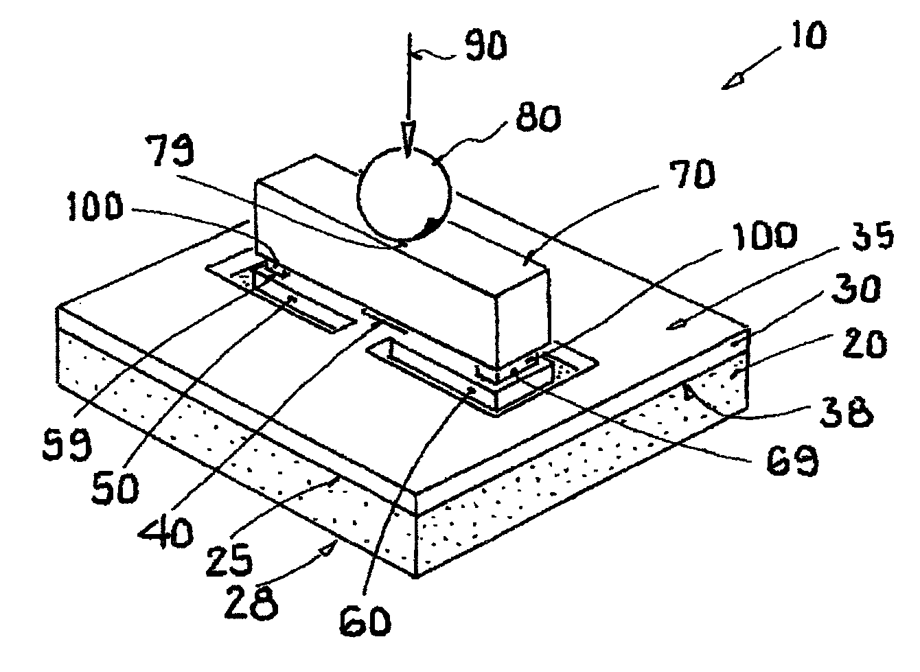
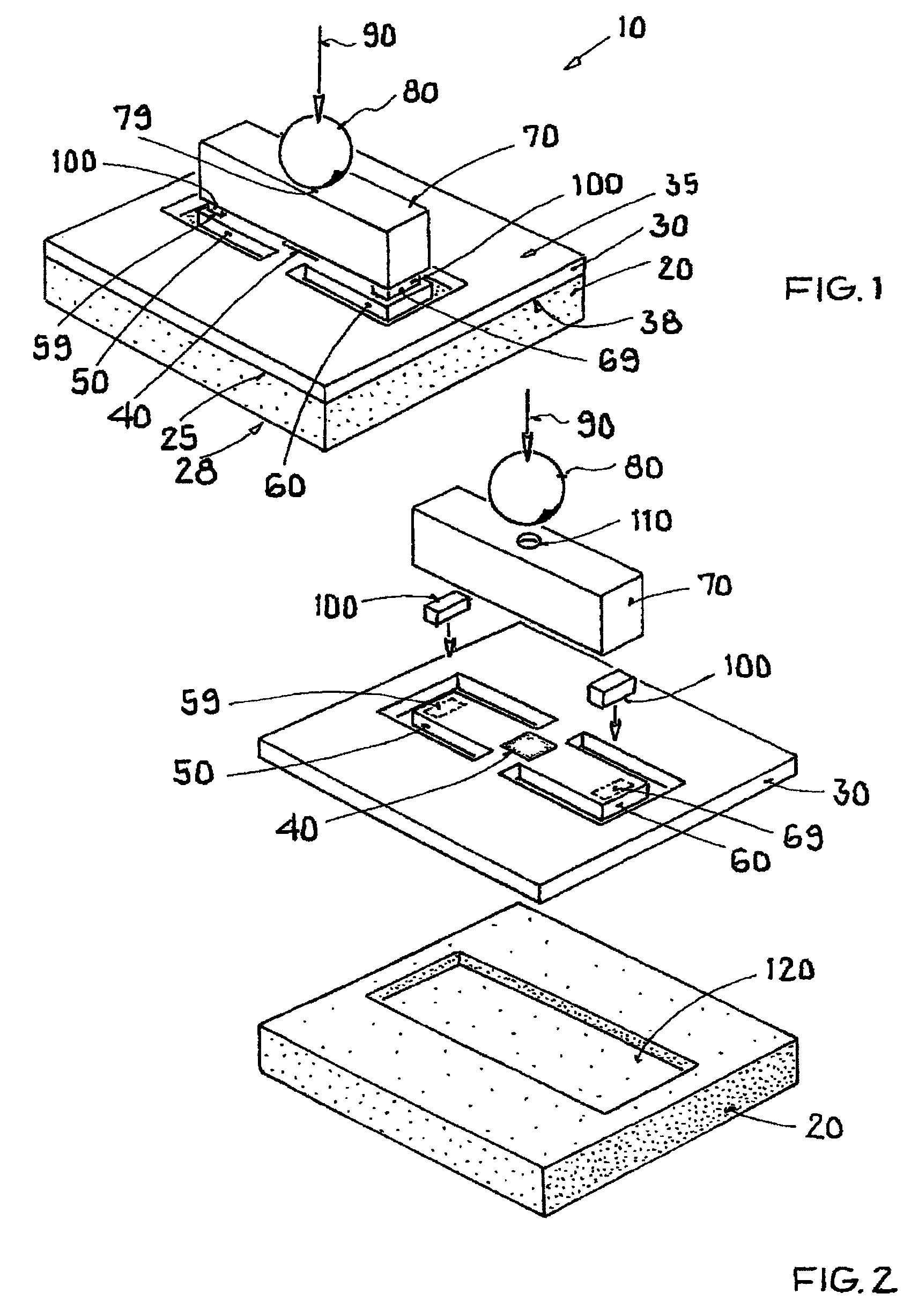
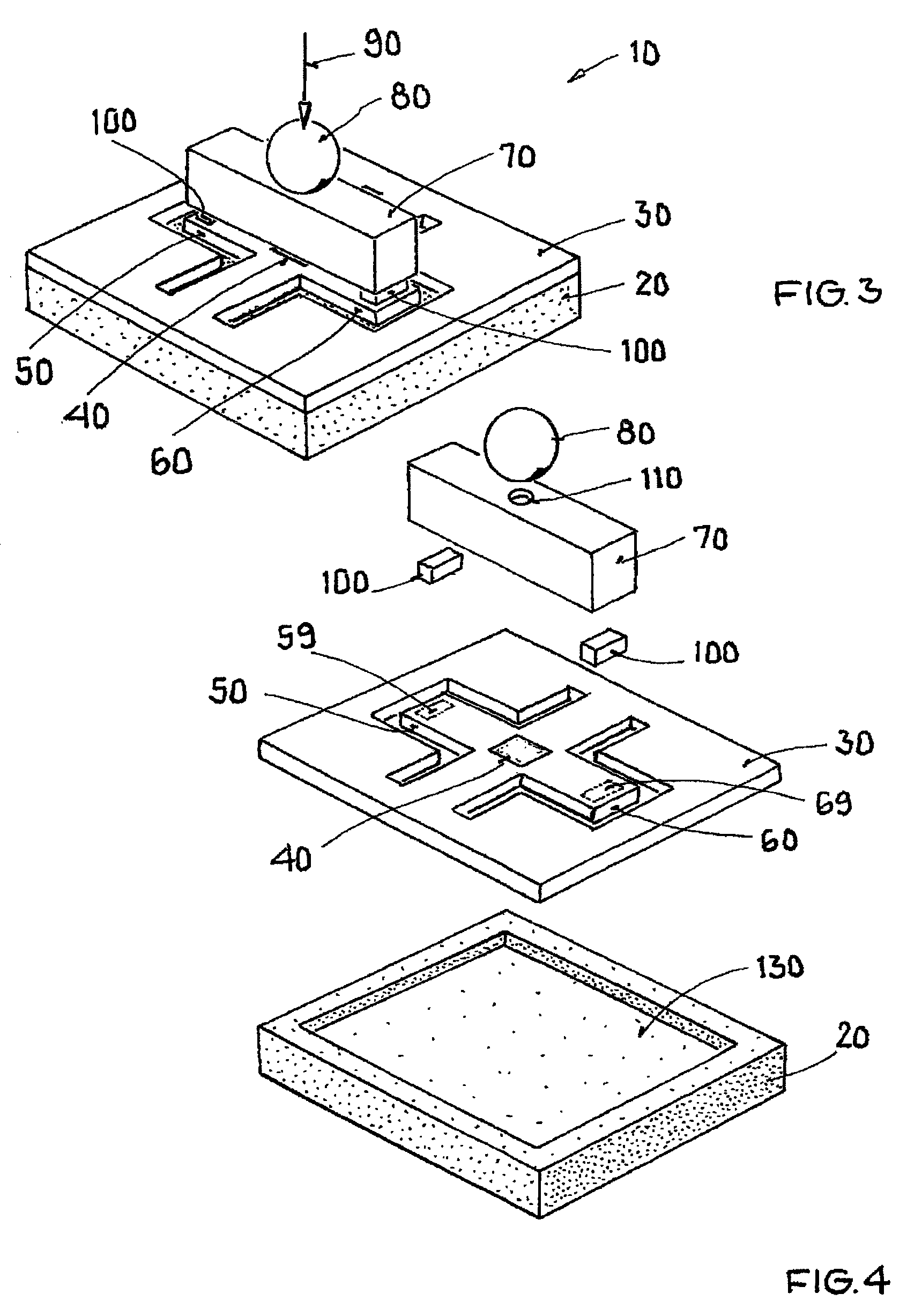
[0030]The illustration in FIG. 1 shows an embodiment of a force sensor 10 according to the invention, which comprises a substrate 20 having a front side 25 and a back side 28, and comprising a semiconductor body 30 having a top surface 35 and a back surface 38, and comprising a piezoresistive element 40 provided on top surface 35 of semiconductor body 30, the semiconductor body being connected to substrate 20 in a force-fit manner. Force sensor 10 furthermore has a first wing 50, first wing 50 being provided on top surface 35 of semiconductor body 30 and having an upper side and bottom side. First wing 50 is largely elastically movable along the normal vector of top surface 35 of semiconductor body 30, wherein first wing 50 is connected to semiconductor body 30 in a force-fit manner, and wherein semiconductor body 30 is designed as an abutment upon a movement of the wing. A first force application area 59 is provided on first wing 50.

[0031]Force sensor 10 furthermore has a second wi...


PUM

PropertyMeasurementUnit
forceaaaaaaaaaa
areaaaaaaaaaaa
flexural strengthaaaaaaaaaa

Abstract

A force sensor comprising a substrate, a semiconductor body, and a piezoresistive element provided on a top surface of the semiconductor body. The semiconductor body is connected to the substrate in a force-fit manner, and includes a first wing which is provided on the top surface of the semiconductor body and being connected to the semiconductor body in a force-fit manner. A first force application area is provided on the first wing. A second wing has a second force application area provided opposite the first wing. The piezoresistive element is disposed between the first wing and the second wing. A force distribution component is connected to the first force application area and the second force application area in a force-fit manner. The force distribution component having a first surface which is oriented away from the top surface of the semiconductor body and includes a third force application area.

Description

[0001]This nonprovisional application claims priority to German Patent Application No. DE 10 2011 112 935.2, which was filed in Germany on Sep. 13, 2011, and to U.S. Provisional Application No. 61 / 548,496, which was filed on Oct. 18, 2011, and which are both herein incorporated by reference.BACKGROUND OF THE INVENTION[0002]1. Field of the Invention[0003]The present invention relates to a force sensor.[0004]2. Description of the Background Art[0005]A force sensor having a piezoresistive element is known from DE 41 37 624, which corresponds to U.S. Pat. No. 5,600,074. Among other things, this publication discloses a wing-like configuration in which an application of force is provided in the vicinity of the wing abutment. An integrated circuit is furthermore disposed on the outer end of the wing. By applying force close to the abutment, an attempt is made to keep the integrated circuit as free of mechanical stress as possible.SUMMARY OF THE INVENTION[0006]It is therefore an object of t...

Claims


Application Information

Patent Timeline
Patent Type & Authority Patents(United States)
IPC IPC(8): G01L9/00G01L1/18G01L1/10
CPCG01L9/0054G01L1/18
Inventor BAUMANN, MARCRUTHER, PATRICKPETER, ALEXANDERPAUL, OLIVER
Owner TDK MICRONAS GMBH
Why Eureka
Try Eureka