
Method and device for diagnosis of sensor faults for determination of angular position of polyphase rotary electrical machine

Active Publication Date: 2014-12-23
VALEO EQUIP ELECTRIC MOTEUR
View PDF6 Cites 0 Cited by
  • Summary
  • Abstract
  • Description
  • Claims
  • Application Information

AI Technical Summary

Benefits of technology

The invention provides a method for diagnosing faults in the sensors that measure the rotational position of a polyphase rotary electrical machine, such as an alternator-starter. This method aims to overcome the shortcomings of previous methods without adding much complexity or cost to the electronic circuits involved.

Problems solved by technology

In practice, these functioning conditions, which can be classified as “ideal” are rarely fulfilled.
Consequently, again in practice, the above-described method often proves to be unsatisfactory.
However this loop is very sensitive to small saturations, and cannot detect any error in the presence of signals with a very low amplitude (including the errors caused by short-circuits of the sensor or connectors which are disconnected).
In addition, in certain-practical embodiments, the tracking loop error signal is contaminated by substantial noise as the result of lack of calibration and low accuracy caused by the simplification of the electronic circuits used.
Consequently, a certain number of faults cannot be diagnosed.
However, this method makes it necessary to resort to additional electronic circuits such as, either to measure the signal VS1 or to measure the complete sum of signals, which increases the complexity of the diagnostic device, and makes it more costly.
In addition, for the reason previously given (low accuracy due to the lack of calibration), it is necessary to accept a substantial margin as far as the detection thresholds are concerned.
Consequently, a certain number of faults cannot be diagnosed.

Method used


Image

  • Method and device for diagnosis of sensor faults for determination of angular position of polyphase rotary electrical machine
  • Method and device for diagnosis of sensor faults for determination of angular position of polyphase rotary electrical machine
  • Method and device for diagnosis of sensor faults for determination of angular position of polyphase rotary electrical machine

Examples


Embodiment Construction

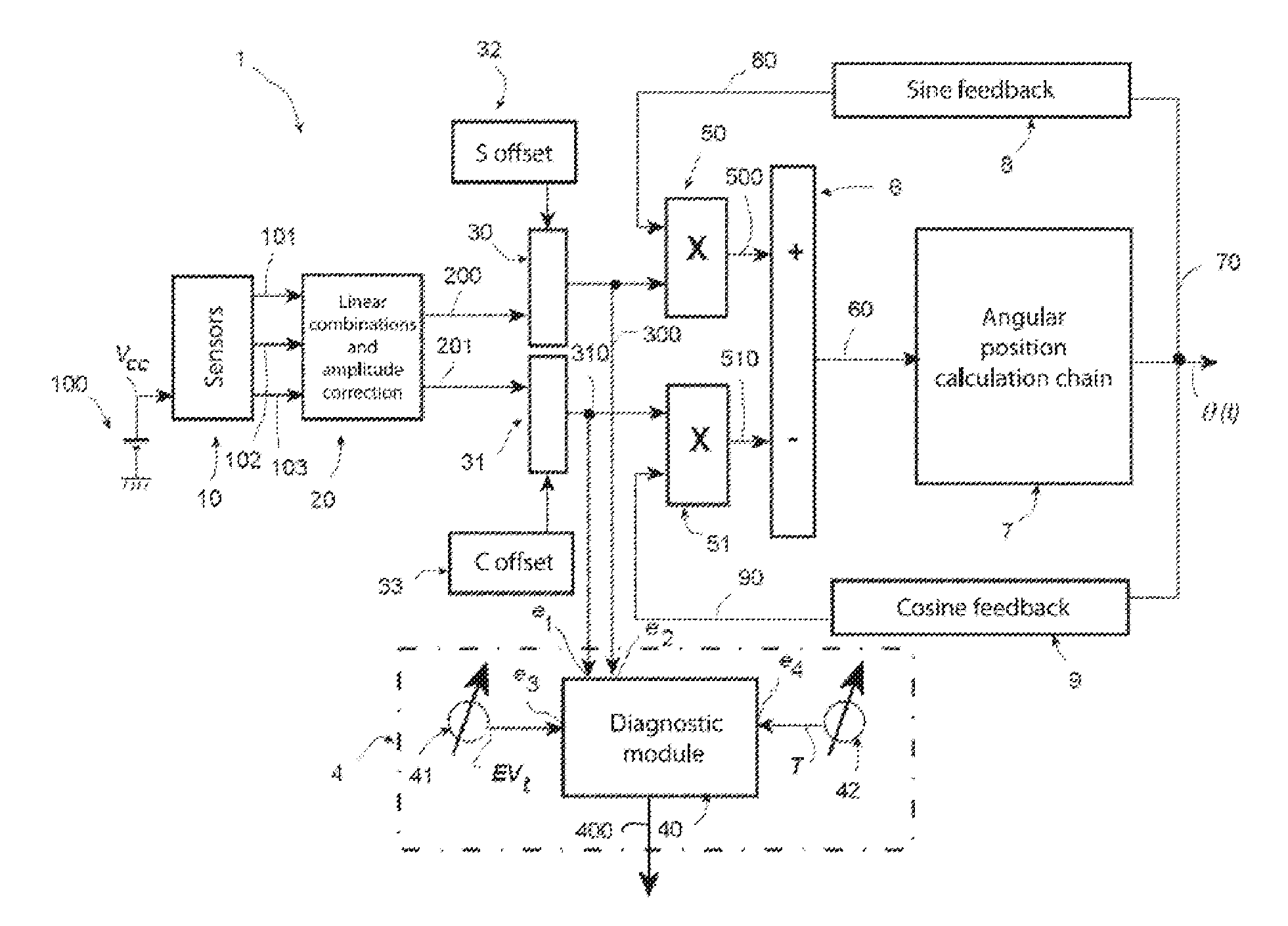
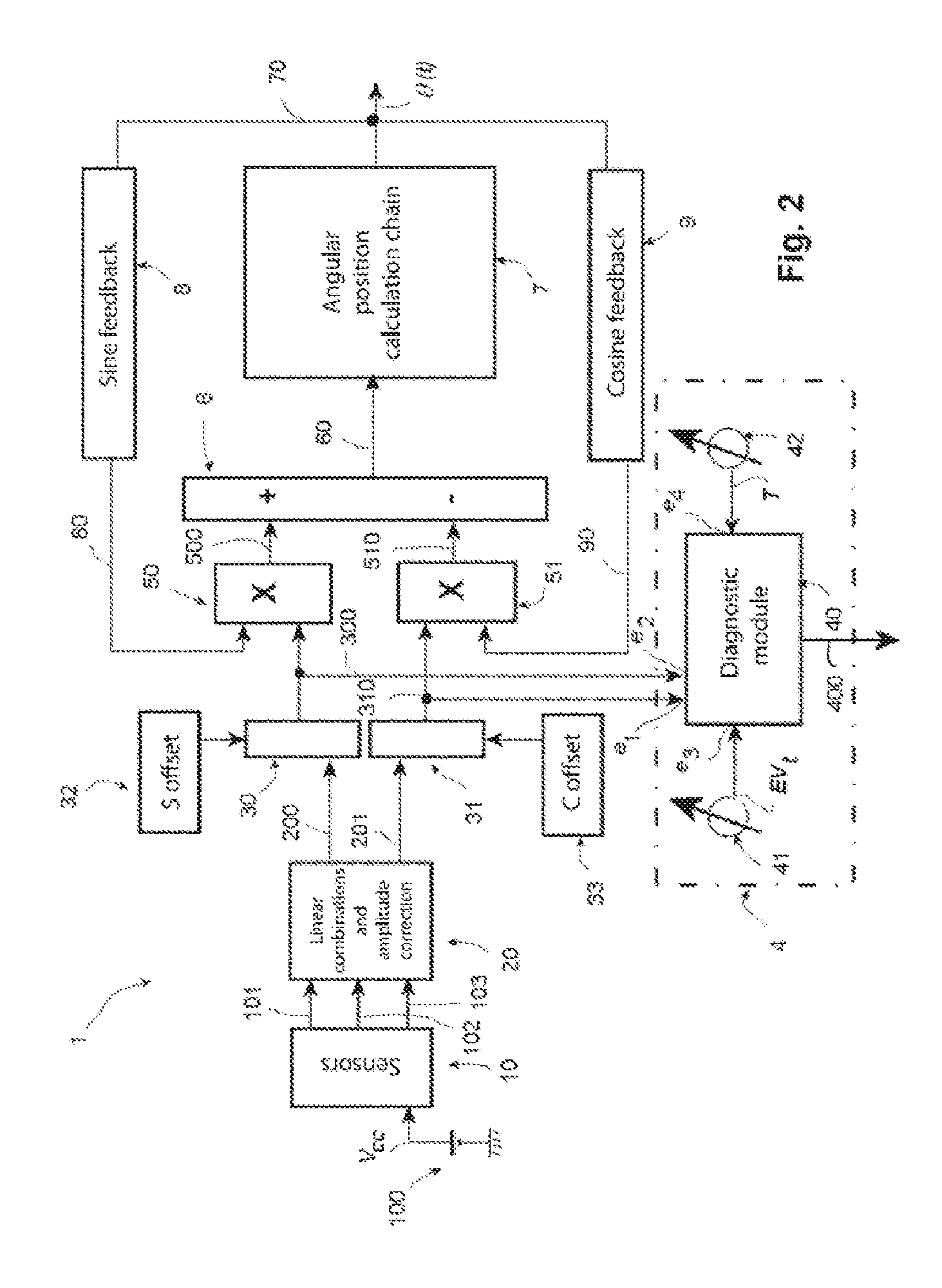
[0083]Hereinafter, without in any way limiting the scope of the invention, unless otherwise stated, the context of its preferred embodiment will apply, i.e. the case of a system for determination of the angular position of a rotor of an alternator-starter which implements a system for control between a measured angular position and an estimated angular position.

[0084]FIG. 2 illustrates an example of a system 1 for determination of the angular position of a rotor of an alternator-starter according to the architecture described in the aforementioned French patent application no. 0853359. It also incorporates a device 4 for diagnosis of the functioning faults of the angular position measurement sensors according to a preferred embodiment of the invention.

[0085]The alternator-starter (not illustrated in this figure) can be of a type which is altogether similar to the prior art, or identical. The sensors in the block 10 are constituted for example by three Hall-effect sensors disposed at...


PUM


Abstract

Disclosed is a method and device for diagnosis of functioning faults caused by the angular position measurement sensors of the rotor of a polyphase rotary electrical machine comprising a stator, in particular of the alternator-starter type. The diagnosis is obtained by carrying out direct measurements of pairs of sine and cosine signals determined on the basis of linear combinations of the polyphase signals provided by these sensors. This measurement therefore does not make it necessary to know the exact value of the speed of the machine. The diagnosis of functioning faults caused by the angular position measurement sensors requires only the execution of elementary logic operations, i.e. the determination of the “true” or “false” logic states of two inequality equations.

Description

CROSS-REFERENCE TO RELATED APPLICATIONS AND CLAIM TO PRIORITY[0001]This application relates to International Application No. PCT / FR2010 / 050392 filed Mar. 8, 2010 and French Patent Application No. 09 / 52021 filed Mar. 31, 2009, of which the disclosures are incorporated herein by reference and to which priority is claimed.FIELD OF THE INVENTION[0002]The invention relates to a method for diagnosis of functioning faults of sensors for determination of the angular position of a polyphase rotary electrical machine comprising a stator.[0003]The invention also relates to a device for implementation of a method of this type.BACKGROUD OF THE INVENTION[0004]It applies more particularly to reversible machines, known as alternator-starters which are used in the automobile industry, in both alternator and engine mode.[0005]Within the context of the invention, the term “polyphase” relates more particularly to three-phase or hexaphase rotary electrical machines, but it can also relate to two-phase r...

Claims


Application Information

Patent Timeline
IPC IPC(8): G01D3/08G01B7/30
CPCG01D3/08
Inventor LABISTE, LAURENT
Owner VALEO EQUIP ELECTRIC MOTEUR
Learn More