Active optical device using phase change material

a phase change material and active optical technology, applied in the field of active optical devices using phase change materials, can solve the problems of slow speed at which the refractive index can be changed, limitation of the size of the slm, and often needed complicated structures, and achieve the effect of quick modulation

Active Publication Date: 2014-12-23
SAMSUNG ELECTRONICS CO LTD
View PDF13 Cites 7 Cited by
  • Summary
  • Abstract
  • Description
  • Claims
  • Application Information

AI Technical Summary

Benefits of technology

[0007]One or more embodiments provide active optical devices for quickly modulating a refractive index according to an external signal.

Problems solved by technology

Accordingly, in order to control the path of light in an optical system in a desired way, complicated structures are often needed.
In such SLMs, however, the speed at which the refractive index can be changed may be too slow for many functions, and there is a limitation in the size of the SLM.

Method used


Image

  • Active optical device using phase change material
  • Active optical device using phase change material
  • Active optical device using phase change material

Examples


Embodiment Construction

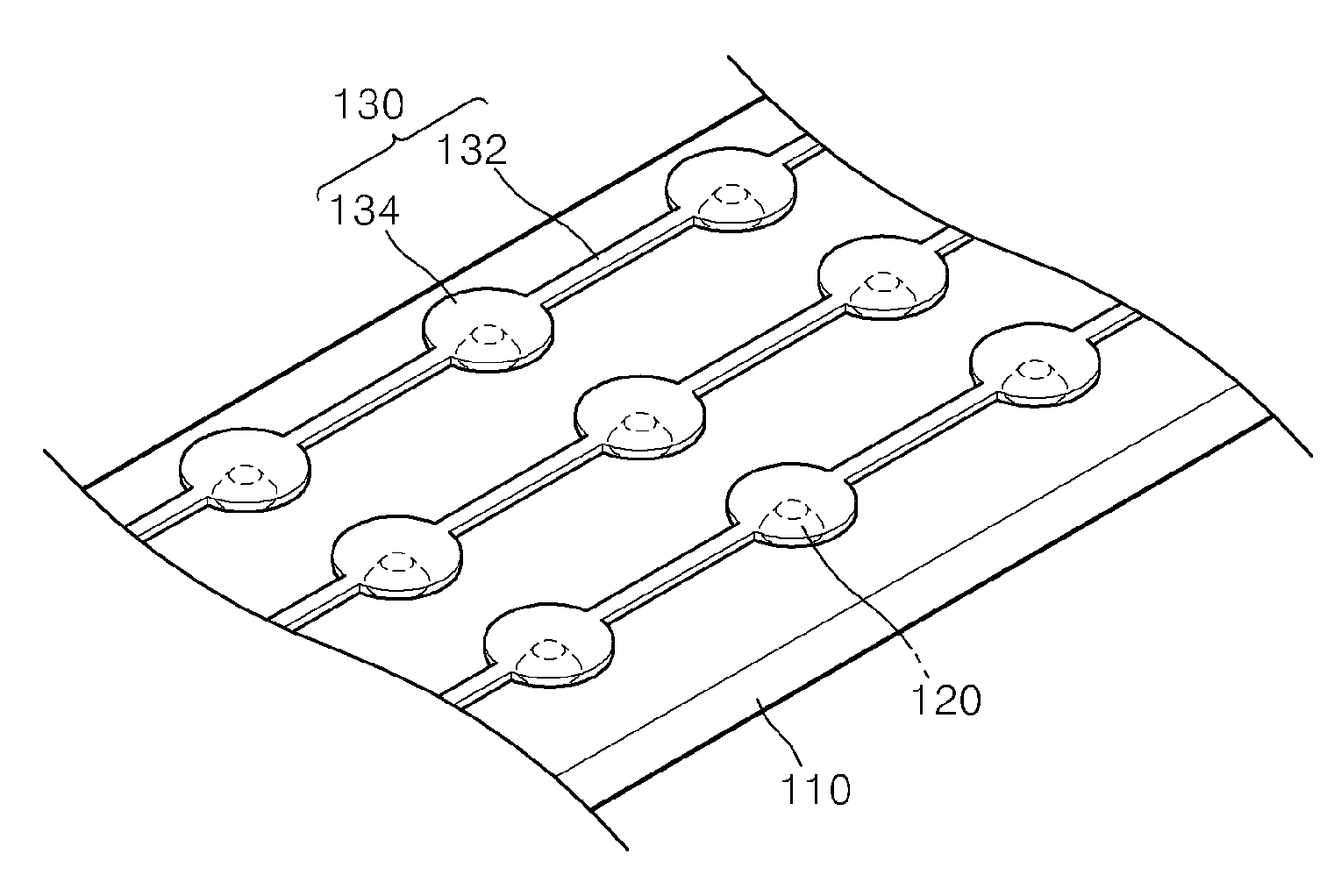
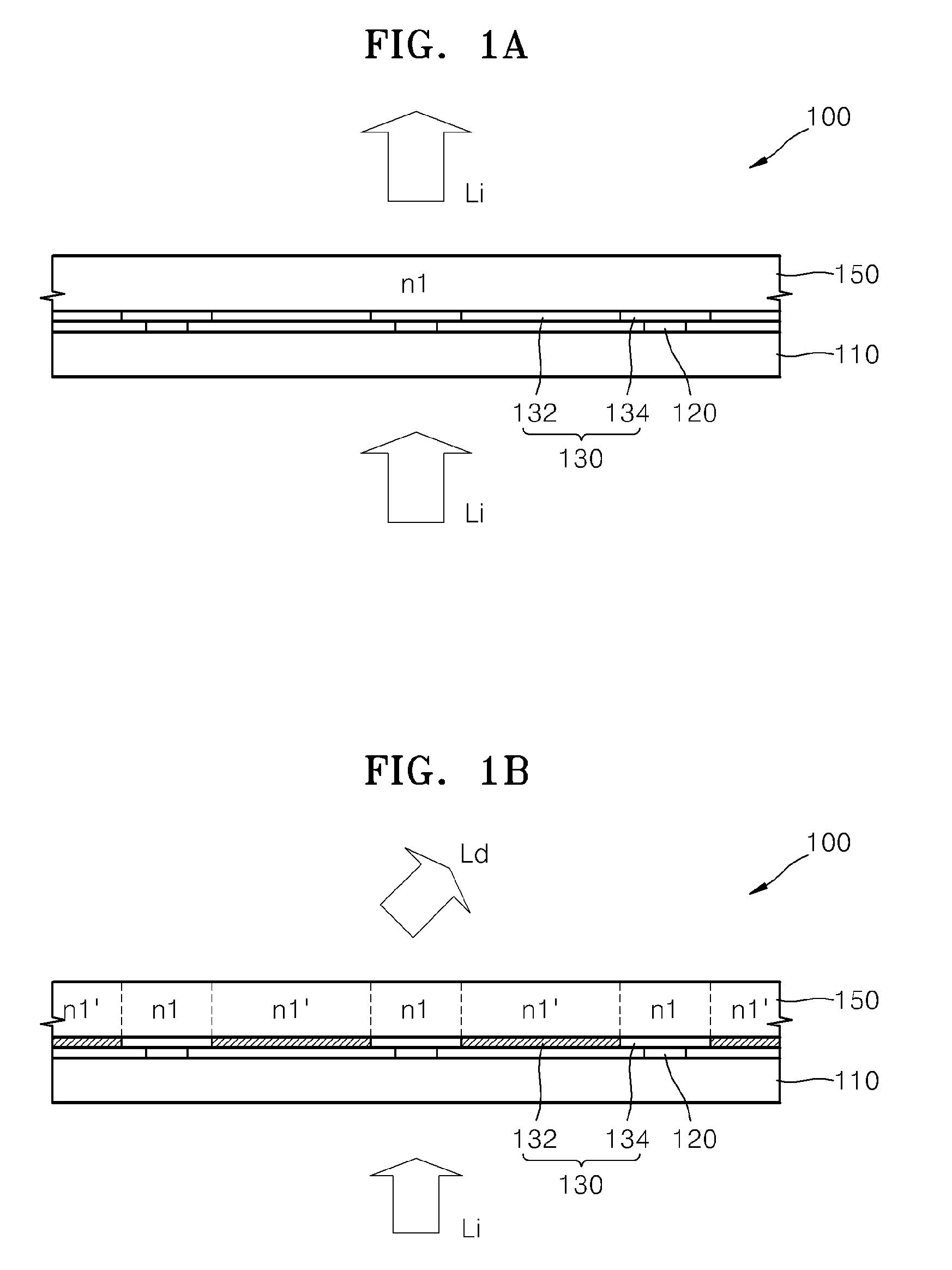
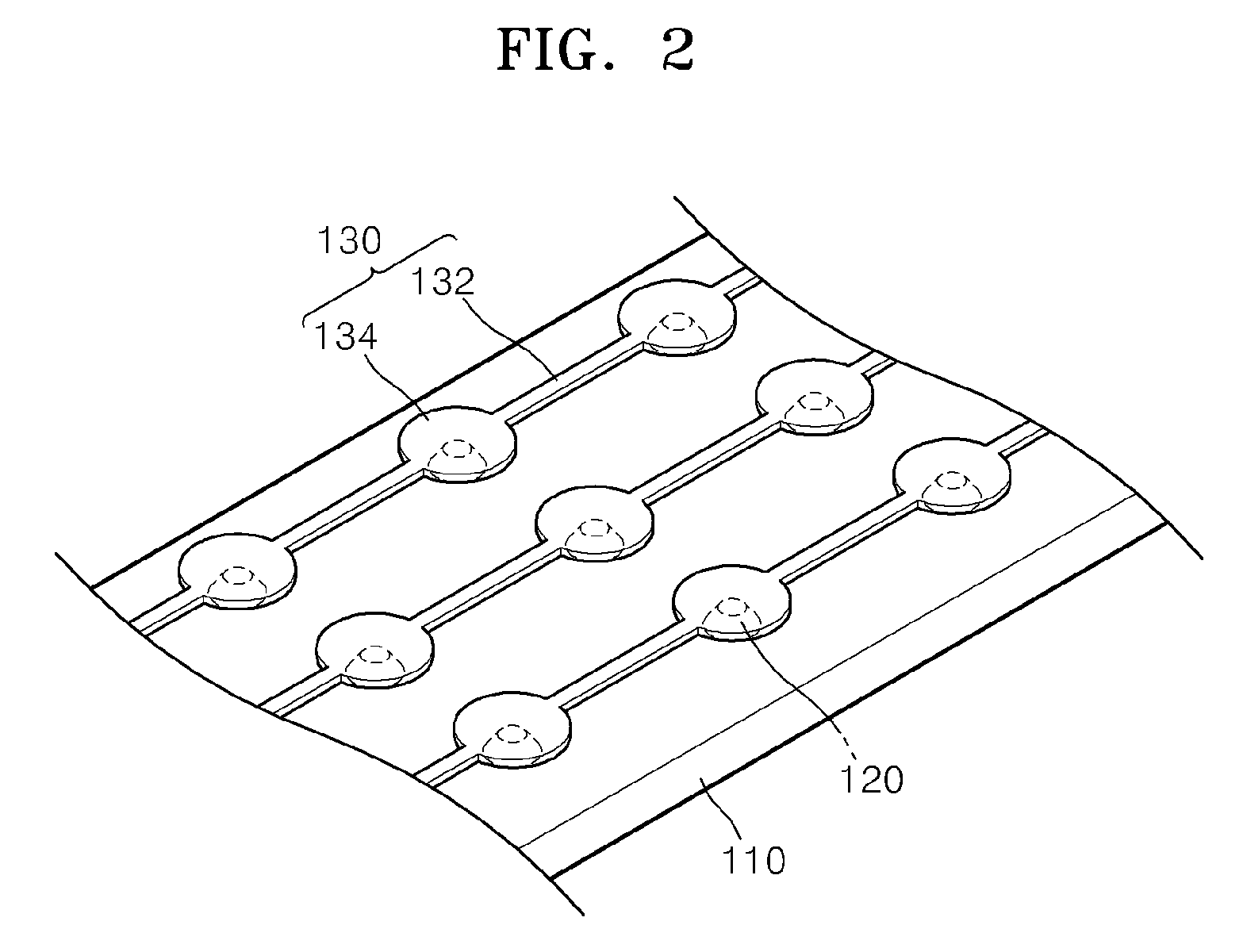
[0023]Reference will now be made in detail to embodiments, examples of which are illustrated in the accompanying drawings, wherein like reference numerals refer to like elements throughout, and sizes of elements in the drawings may be exaggerated for clarity and ease of description. In this regard, the present embodiments may have different forms and should not be construed as being limited to the descriptions set forth herein. Accordingly, the embodiments are merely described below, by referring to the figures, to explain exemplary aspects of the present description.

[0024]In the following embodiments, a phase change material having a phase which varies according to temperature is used. That is, an active optical device is based on the concept that the permittivity of a material varies according to the phase of the material which itself varies according to an external temperature. The refractive index of the material thereby changes with a change in the permittivity of the material....


PUM

PropertyMeasurementUnit
threshold temperatureaaaaaaaaaa
refractive indexaaaaaaaaaa

Abstract

An active optical device is provided. The active optical device includes an optically variable layer having a refractive index which changes according to temperature; and a temperature control unit that controls a temperature of one or more regions of the optically variable layer.

Description

CROSS-REFERENCE TO RELATED APPLICATION[0001]This application claims priority from Korean Patent Application No. 10-2010-0115764, filed on Nov. 19, 2010, in the Korean Intellectual Property Office, the disclosure of which is incorporated herein in its entirety by reference.BACKGROUND[0002]1. Field[0003]The present disclosure relates to active optical devices using a phase change material.[0004]2. Description of the Related Art[0005]Optical devices, such as a lens, a mirror, or a prism, are variously used for modulating the path of light in an optical system. In general, optical devices are formed of materials having fixed refractive indexes, and the effect the device has on the path of light is based, in large part, on the shape of the device. Accordingly, in order to control the path of light in an optical system in a desired way, complicated structures are often needed.[0006]Such complexity may be addressed by using a spatial light modulator (SLM) capable of performing functions of...

Claims


Application Information

Patent Timeline
Patent Type & Authority Patents(United States)
IPC IPC(8): G02B26/06G02F1/29G02F1/01
CPCG02F1/0147G02F2201/305G02F2202/32G02F1/292G02B26/00G02B26/06G02F1/19
Inventor KIM, SUN-ILCHOI, JUN-HEEKIM, JONG-MIN
Owner SAMSUNG ELECTRONICS CO LTD
Why Eureka
Try Eureka