Control method and device of two-way electromagnetic force control valve for common rail flow control

An electromagnetic force and control valve technology, applied in electrical control, engine control, fuel injection control, etc., can solve the two-way overshoot of rail pressure, affect the pressure regulation effect of the high-pressure common rail fuel supply system, and affect the closing of the fuel metering valve, etc. problem, to achieve the effect of rapid displacement and accurate control, improvement of two-way overshoot phenomenon, and accurate adjustment

Inactive Publication Date: 2018-07-17
BEIJING INSTITUTE OF TECHNOLOGYGY
View PDF5 Cites 7 Cited by
  • Summary
  • Abstract
  • Description
  • Claims
  • Application Information

AI Technical Summary

Problems solved by technology

[0003] The existing fuel metering valves are all one-way electromagnetic force control valves, and the electromagnetic force can only drive the spool of the fuel metering valve to move in the direction of opening the valve port. In addition, during the return process of the spool, the electromagnetic force Hysteresis affects the closing of the fuel metering valve
Therefore, during the establishment of the rail pressure, it often causes two-way overshoot of the rail pressure, which affects the pressure regulation effect of the high-pressure common rail oil supply system.

Method used


Image

  • Control method and device of two-way electromagnetic force control valve for common rail flow control
  • Control method and device of two-way electromagnetic force control valve for common rail flow control
  • Control method and device of two-way electromagnetic force control valve for common rail flow control

Examples


Embodiment Construction

[0026] In order to make the purpose, technical solutions and advantages of the embodiments of the present invention clearer, the technical solutions in the embodiments of the present invention will be clearly described below in conjunction with the accompanying drawings in the embodiments of the present invention. Obviously, the described embodiments are the Some, but not all, embodiments are invented. Based on the embodiments of the present invention, all other embodiments obtained by persons of ordinary skill in the art without making creative efforts belong to the protection scope of the present invention.

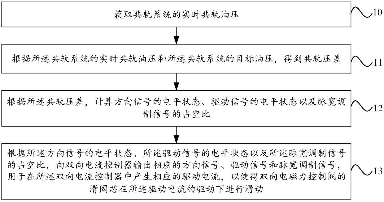
[0027] figure 1 The flow chart of the control method for the two-way electromagnetic force control valve used for common rail flow control provided by the embodiment of the present invention, as shown in figure 1 As shown, the method includes:

[0028] Step 10, obtaining the real-time common rail oil pressure of the common rail system;

[0029] Step 11. Obtain the co...


PUM


Abstract

The embodiment of the invention provides a control method and device of a two-way electromagnetic force control valve for common rail flow control. The method comprises the steps that real-time commonrail oil pressure of a common rail system is obtained; common rail differential pressure is obtained according to the real-time common rail oil pressure of the common rail system and target oil pressure of the common rail system; the duty ratio of a direction signal, a driving signal and a pulse width modulation signal is calculated according to the common rail differential pressure; and the corresponding direction signal, driving signal and pulse width modulation signal are output to a bidirectional current controller according to the electrical level state of the direction signal, the electrical level state of the driving signal and the duty ratio of the pulse width modulation signal, and are used for generating a corresponding driving current in the bidirectional current controller, sothat a sliding valve core of the two-way electromagnetic force control valve is driven by the driving current to slide. The control method and device of the two-way electromagnetic force control valve for the common rail flow control can achieve fast and accurate adjustment of the common rail pressure of the high pressure common rail oil supply system.

Description

technical field [0001] Embodiments of the present invention relate to the field of power technology, and in particular to a control method and device for a bidirectional electromagnetic force control valve used for common rail flow control. Background technique [0002] In the high-pressure common rail fuel supply system, the fuel metering valve is an important link in the control of the fuel intake of the common rail pipe, and its working characteristics have a very important impact on the establishment of rail pressure. [0003] The existing fuel metering valves are all one-way electromagnetic force control valves, and the electromagnetic force can only drive the spool of the fuel metering valve to move in the direction of opening the valve port. In addition, during the return process of the spool, the electromagnetic force Hysteresis affects the closing of the fuel metering valve. Therefore, in the process of establishing the rail pressure, the two-way overshoot of the r...

Claims


Application Information

Patent Timeline
Patent Type & Authority Applications(China)
IPC IPC(8): F02D41/38F02D41/22F02M63/00F02D41/20
CPCF02D41/221F02D41/3836F02D2041/2027F02M63/0017F02M63/004
Inventor 左哲杜猛谢军姚建伟赵振峰张付军
Owner BEIJING INSTITUTE OF TECHNOLOGYGY
Why Eureka
Try Eureka