
Method and apparatus for voice recognition unit simulation

a voice recognition and unit simulation technology, applied in the field of call calculators, can solve the problems of complex hardware setup, rigid application development environment, additional expense, etc., and achieve the effect of reducing complexity, cost effective and reducing cos

Active Publication Date: 2014-12-23
WEST TECH GRP LLC
View PDF24 Cites 2 Cited by
  • Summary
  • Abstract
  • Description
  • Claims
  • Application Information

AI Technical Summary

Benefits of technology

[0010]There can be various components assembled to form the present invention, which can remedy many of the short comings and problem areas in the Interactive Voice Recognition (IVR) arena. By way of a high level overview of the present invention, on the basis of its functionalities, the various components can be categorized as follows. 1.) Simulated IVR Components; 2.) Emulated Telecom, Voice and Recognition Components; 3.) Use of external control messages rather than telecom in a telephony platform; 4.) Seamless substitution of the simulated component in place of a real unit made possible by providing the software hooks (event notification) to the appropriate part of the system; 5.) Development and Test of multiple components of the telephony platform using external means; and 6.) State machine synchronization utilized to facilitate the reproduction of real world case scenario and predictability of the outcome.
[0013]The XML driven call engine can simulate calls with millisecond precision and hence able to replicate the call scenario to the closest approximation. Multiple components of the simulator is closely watched by a watcher application. Multiple simulators can be integrated together with the concept of ‘dialer’ acting as a management tool that will monitor the different units. This way it is possible to generate a large volume for the load test.
[0014]The simulator design for the present invention is very cost effective (ie., does not require any special hardware) and millions of calls can be generated for ‘zero cost’ paring the usage of existing desktop and intranet hardware. These and other advantageous features of the present invention will be in part apparent and in part pointed out herein below.

Problems solved by technology

Traditionally, telephony application development involves complicated hardware set up.
This complicated hardware set up includes telephony and media gateway, and speech servers.
This situation results in additional expense and a rigid application development environment.

Method used


Image

  • Method and apparatus for voice recognition unit simulation
  • Method and apparatus for voice recognition unit simulation
  • Method and apparatus for voice recognition unit simulation

Examples


Embodiment Construction

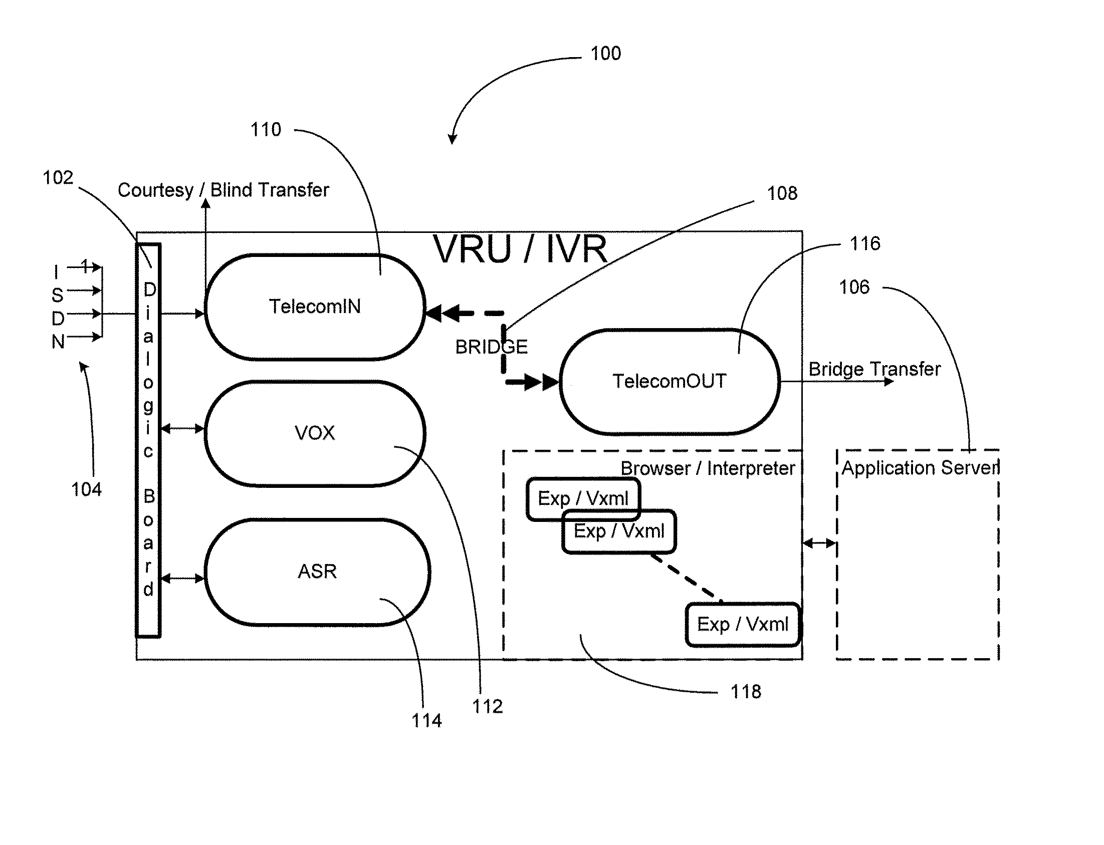
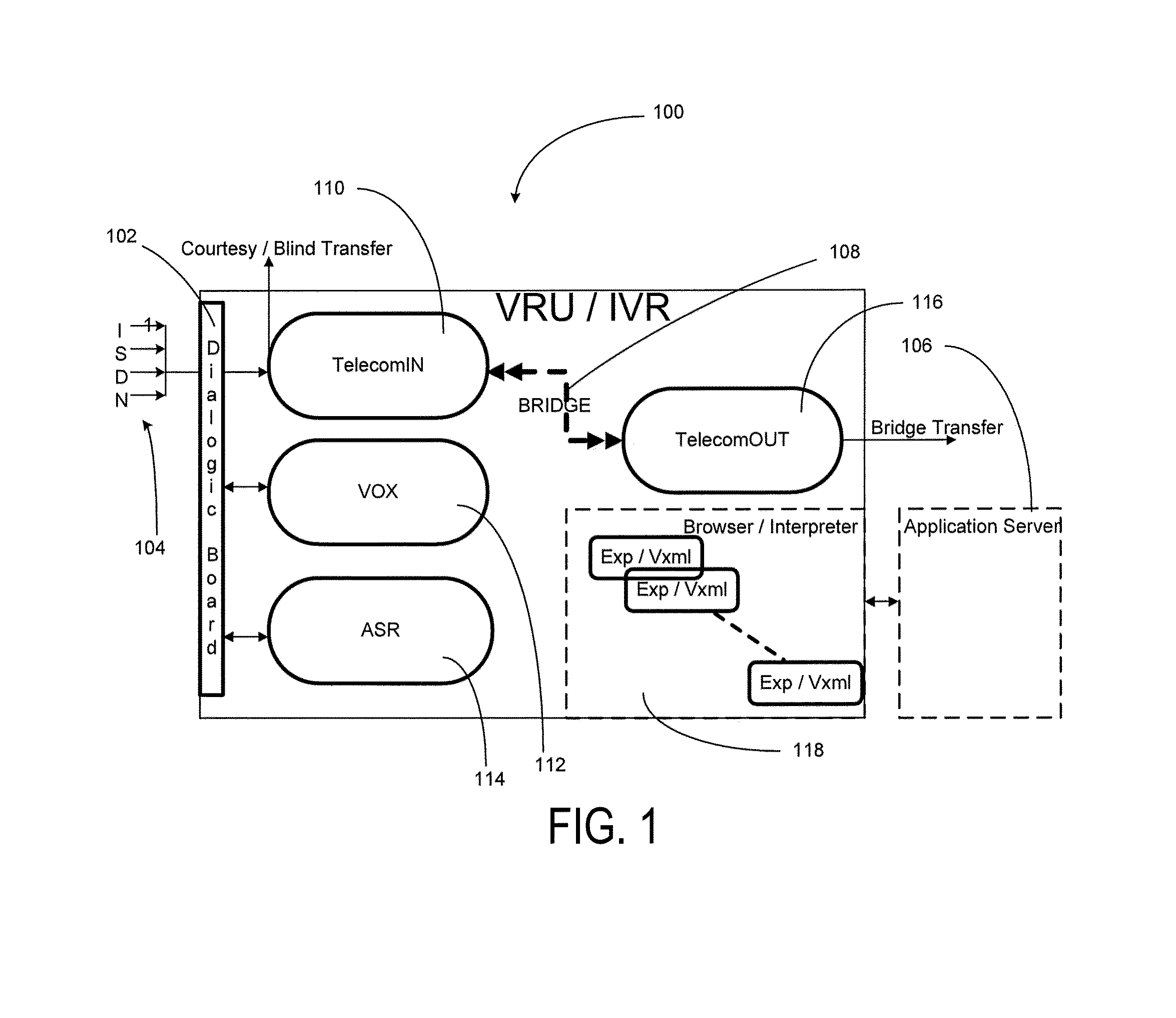
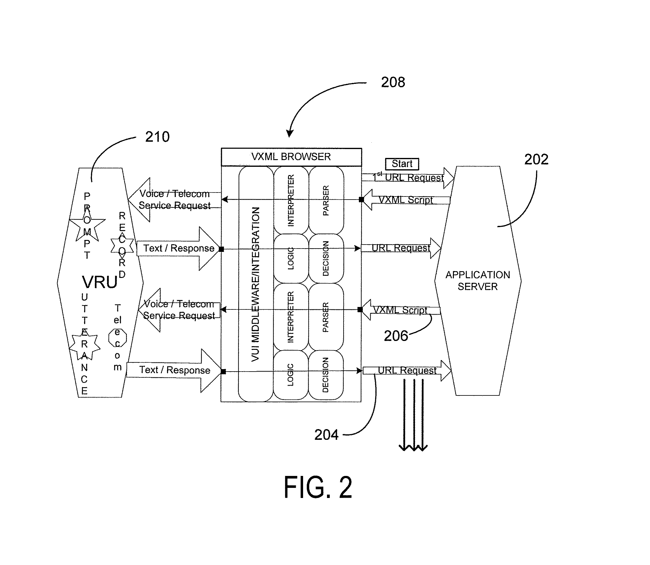
[0091]According to the embodiment(s) of the present invention, various views are illustrated in FIG. 1-24 and like reference numerals are being used consistently throughout to refer to like and corresponding parts of the invention for all of the various views and figures of the drawing. Also, please note that the first digit(s) of the reference number for a given item or part of the invention should correspond to the Fig. number in which the item or part is first identified.

[0092]There are various components integrated to form the proposed invention, which are designed to remedy many of the problem areas in the Interactive Voice Recognition (IVR) arena. On a high level, on the basis of its functionalities, the various components can be categorized as follows:[0093]Simulated Components[0094]Emulated components[0095]Process Controller (Application Engine)[0096]System Integrity Module[0097]External Functionality Modules[0098]Call Calculator

[0099]The majority of the modules in the tradi...


PUM


Abstract

A call calculator and method thereof used to automate testing of a voice self service platform. The call calculator may have functional logic to calculate an estimated call load. The type of load may be least one of cyclic, peak, burst, choppy, and sustained. The call calculator may use a set of input parameters of an algorithm to calculate the estimated call load, wherein the algorithm may be based on an integral calculus model.

Description

CROSS-REFERENCE TO RELATED APPLICATIONS[0001]This application is a continuation of U.S. patent application Ser. No. 11 / 759,659, filed on Jun. 7, 2007, entitled METHOD AND APPARATUS FOR VOICE RECOGNITION UNIT SIMULATION, the entirety of which is incorporated herein by this reference in its entirety.BACKGROUND OF INVENTION[0002]1. Field of Invention[0003]This invention relates generally to testing of telecommunication systems and, more particularly, to call calculator having functional logic to calculate an estimated call load.[0004]2. Background Art[0005]Traditionally, telephony application development involves complicated hardware set up. This complicated hardware set up includes telephony and media gateway, and speech servers. In many test environments, the application developer needs to place a telephone call to the platform to test their application. Needless to say, the system developers are also required to do the same. This situation results in additional expense and a rigid a...

Claims


Application Information

Patent Timeline
Patent Type & Authority Patents(United States)
IPC IPC(8): H04M1/24
CPCG06F11/3664H04L43/50H04L41/145G10L15/01G06F9/455G06F30/20H04M1/24H04M3/2227H04M3/493G10L15/00H04M3/4936
Inventor VARMAN, MAHENDRAAKHWAND, MAHMOOD S.
Owner WEST TECH GRP LLC
Learn More