Turbojet engine fan duct suspension using connecting rods with elastomer bushing

Active Publication Date: 2014-12-30
SN DETUDE & DE CONSTR DE MOTEURS DAVIATION S N E C M A
View PDF14 Cites 0 Cited by
  • Summary
  • Abstract
  • Description
  • Claims
  • Application Information

AI Technical Summary

Benefits of technology

The present invention proposes a device for adjusting the length of connecting rods that hold a fan duct in position, without the disadvantages of prior art devices and allows for easy adjustment without offsetting the connecting rods. The device includes an adjusting bushing created by cutting a cylinder from a right angle, which creates a ramp effect and allows for longitudinal movement, or variation in the length of the connecting rod. The bushing includes an elastomer layer that deforms in shear, requiring only limited force. The device also has symmetrical cylinders that make it easier to produce. The eye of the device has a circular shape, increasing rotational flexibility and the maximum angular excursion of the connecting rod. In an alternative form of embodiment, the connecting rod is equipped with a pivot pin passing through its eye, and the pivot pin comprises at least one end stop limiting the movement of the connecting rod in the direction transverse to the direction of its greatest length.

Problems solved by technology

The downside of such a choice is that the system is difficult to fit and that devices for adjusting the length of the connecting rods need to be provided, otherwise mounting becomes impossible.
Under load, this generates an undesirable moment at the attachment of the connecting rod and the bushing therefore has a tendency to turn.
Further, instances of seizure associated with the use of these eccentric bushings have been observed in service.
Finally, the possibilities of adjustment offered by this device are still limited.
However, such a system is difficult to employ and represents a not inconsiderable additional weight.

Method used


Image

  • Turbojet engine fan duct suspension using connecting rods with elastomer bushing
  • Turbojet engine fan duct suspension using connecting rods with elastomer bushing
  • Turbojet engine fan duct suspension using connecting rods with elastomer bushing

Examples


Embodiment Construction

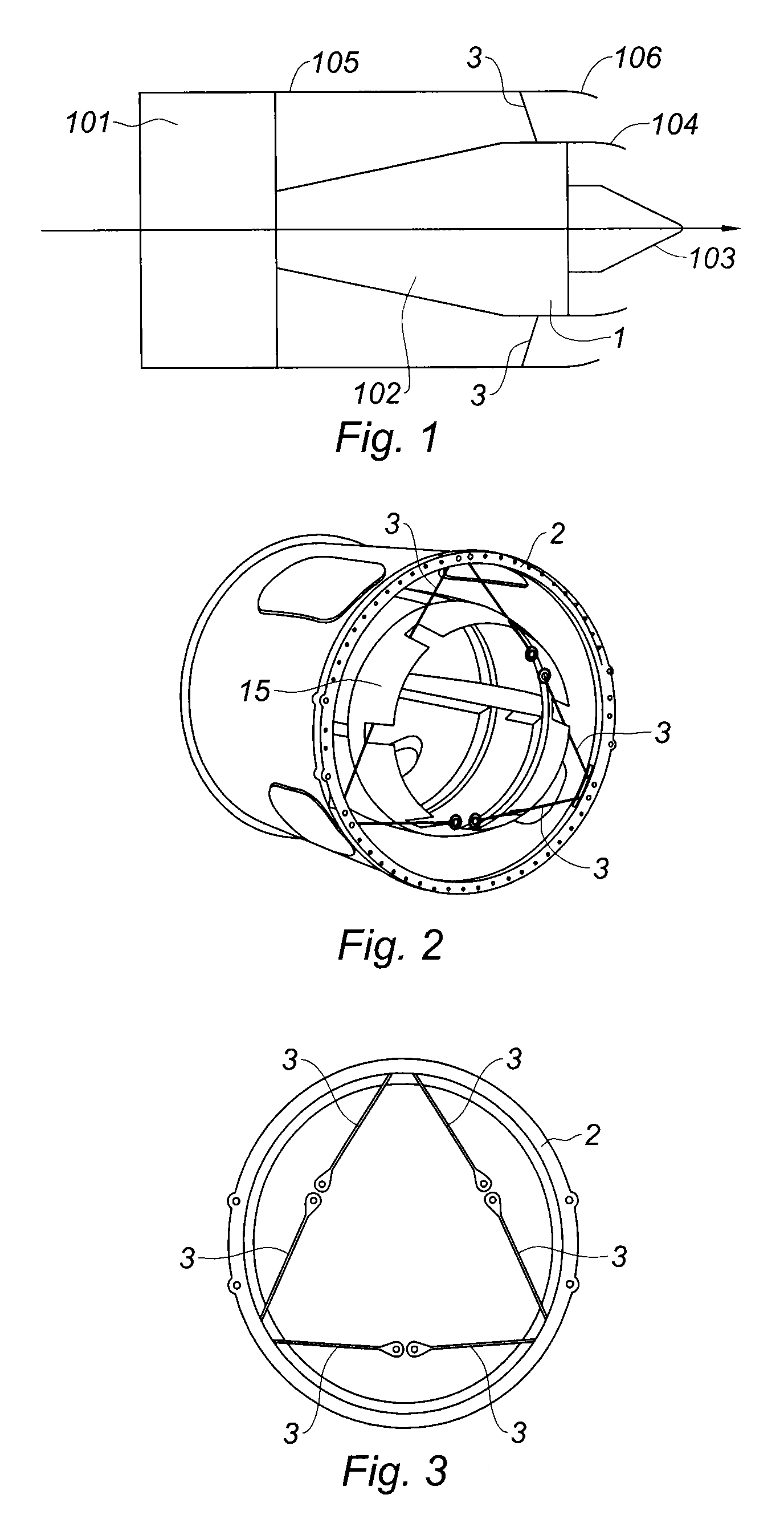
[0033]Reference is made to FIG. 1 which shows a stylized depiction of a bypass turbojet engine comprising a fan 101, a primary spool 102 which at its downstream end has an exhaust case 1 contributing to the structure of the engine, and a tail cone 103. The primary flow, which passes through the primary spool, is ejected in a primary nozzle 104 surrounding the tail cone, while the bypass flow, which comes from the fan, is guided downstream thereof by a fan duct 105 ending in a secondary nozzle 106. The fan duct 105 is attached to the exhaust case 1 by a latticework of connecting rods 3 which are inclined with respect to a radial plane of the engine, the attachment to the fan duct being positioned upstream of the attachment to the exhaust case.

[0034]FIG. 2 shows an inner fan duct 15 which envelops the intermediate case (not visible in the figure) of a bypass turbojet engine. It is cylindrical and itself placed coaxially inside a fan duct 2. The fan duct is supported in the region of t...


PUM

PropertyMeasurementUnit
Lengthaaaaaaaaaa
Shapeaaaaaaaaaa
Metallic bondaaaaaaaaaa

Abstract

Device for adjusting the length of a connecting rod and consisting of a bushing positioned inside an eye of the said connecting rod, the said bushing comprising at least one element in which there is made a bore to act as a support for a pivot pin intended to pass through the eye, characterized in that the said element is a cylinder made of a metallic material covered by a cylinder made of an elastomeric material so as to form with the metallic cylinder a cylinder homothetic with the previous one, the generatrices of the said cylinders being oriented in a direction that is inclined with respect to the longest length of the said connecting rod.

Description

BACKGROUND OF THE INVENTION[0001]1. Field of the Invention[0002]The field of the present invention is that of turbojet engines and of the components that join their various parts together. It relates more particularly to the components that ensure the mechanical integrity of the fan duct of bypass turbojet engines.[0003]2. Description of the Related Art[0004]A propulsion engine, such as a turbojet engine, may be mounted at various locations on the aeroplane, by attaching it to a strut or pylon belonging to the structure thereof. It may thus be suspended under the wing, fixed to the fuselage, generally at the rear, or mounted in the tail using appropriate means of attachment. These means of attachment have the function of transmitting mechanical load between the engine and the structure of the aeroplane. The loads that have to be taken into consideration are notably the weight of the engine along the vertical axis Z, its thrust along the axis X of the engine, and lateral aerodynamic ...

Claims


Application Information

Patent Timeline
IPC IPC(8): F16M13/00
CPCF05D2300/501F05D2300/431Y02T50/672F02C7/20F05B2280/5001F02K3/06Y02T50/60B64D27/10F01D25/04F01D25/28B64D27/40
Inventor BELLABAL, FRANCOIS ROBERTRIVIERE, THOMAS GERARD DANIEL
Owner SN DETUDE & DE CONSTR DE MOTEURS DAVIATION S N E C M A
Why Eureka
Try Eureka