Manipulator

Inactive Publication Date: 2014-12-30
WILFRIED STROTHMANN MASCHENBAU & HANDHABUNGSTECHN
View PDF11 Cites 6 Cited by
  • Summary
  • Abstract
  • Description
  • Claims
  • Application Information

AI Technical Summary

Benefits of technology

The present invention provides a manipulator that allows a movement of a work piece with many degrees of freedom and low expense of time and energy. The manipulator has a supplemental arm that can be extended and pivoted around two axes to provide a high flexibility. The supplemental arm has a tool support that can be moved freely and turns around different axes to provide additional degrees of freedom for the tool. The construction of the manipulator provides advantages in terms of its building height and the movements of the workpiece can be performed with relatively low effort of time and energy. Overall, the present invention Compensates the disadvantages of foldable manipulator arms and reduces the danger of collision of folded parts with the support basis of the molding press.

Problems solved by technology

For this reason this is a common problem to transfer relatively large work pieces from one molding press into another.
If manipulators of the above kind are used for this purpose, comprising foldable arms, the support basis of the adjacent molding presses as well as the support of the manipulator itself obstruct the movement, because the manipulator arm follows a circular arc path during the pivoting movement with its outer end and approaches the basis of the molding presses.
Moreover, another problem is related to the construction of such manipulators, because their movement during the transfer of the work pieces is relatively time consuming and takes much energy.
However, the known linear robots only comprise very few degrees of freedom in the movement of the work pieces, and so they are not suited for the use in a molding press line.
Pivot arm manipulators as well as linear robots both have the common problem that the tool support at the end of the manipulator arm has a construction height that makes the insertion of work pieces in a relatively shallow space within the molding press very difficult.

Method used


Image

  • Manipulator
  • Manipulator
  • Manipulator

Examples


Embodiment Construction

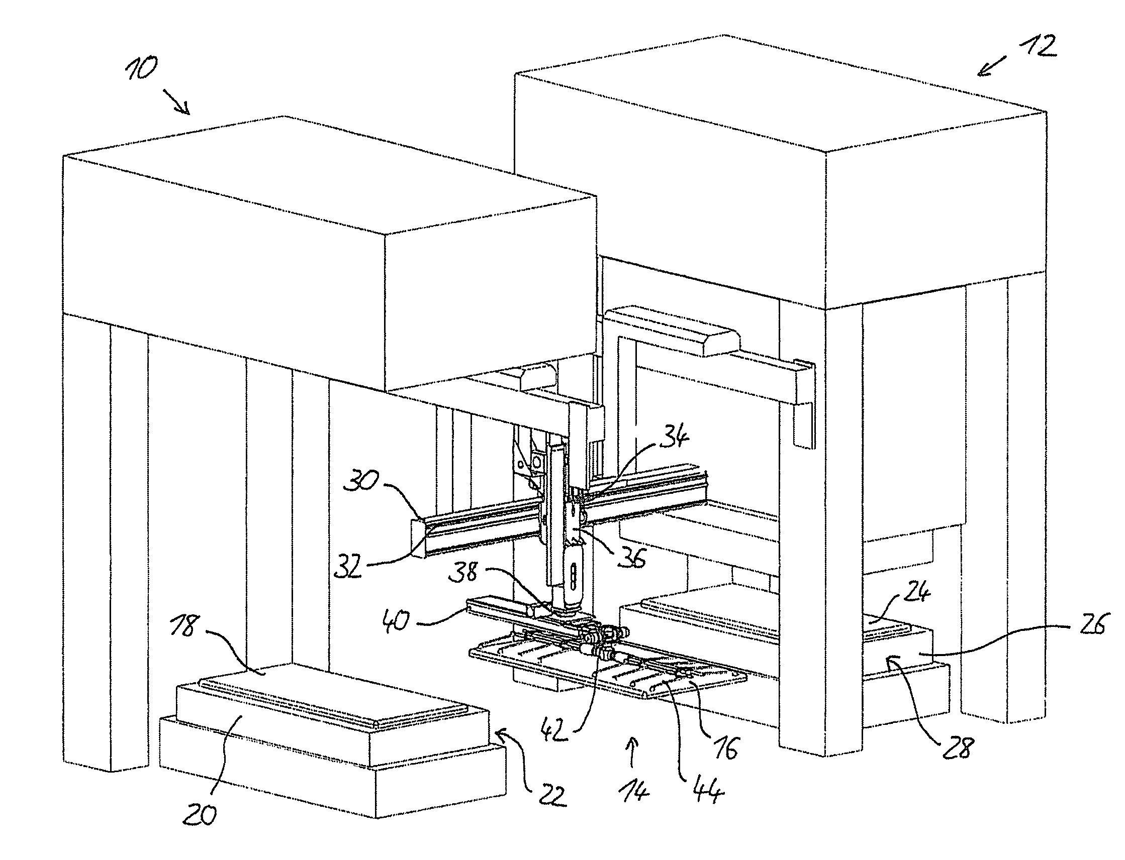
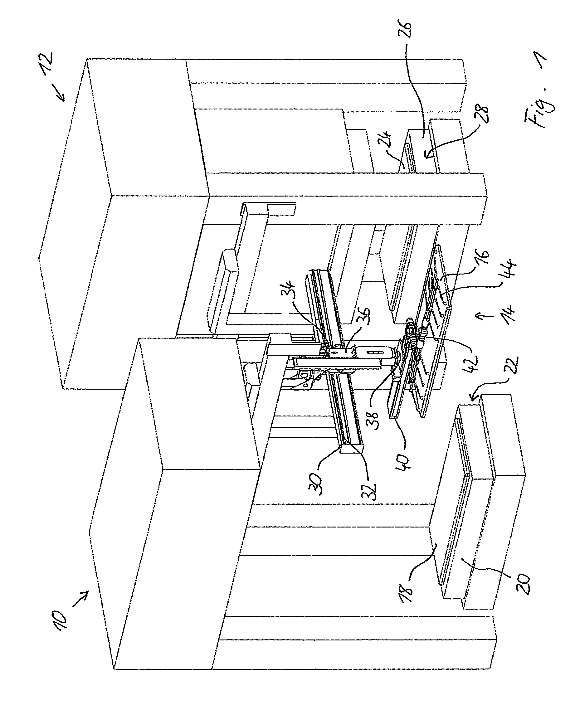
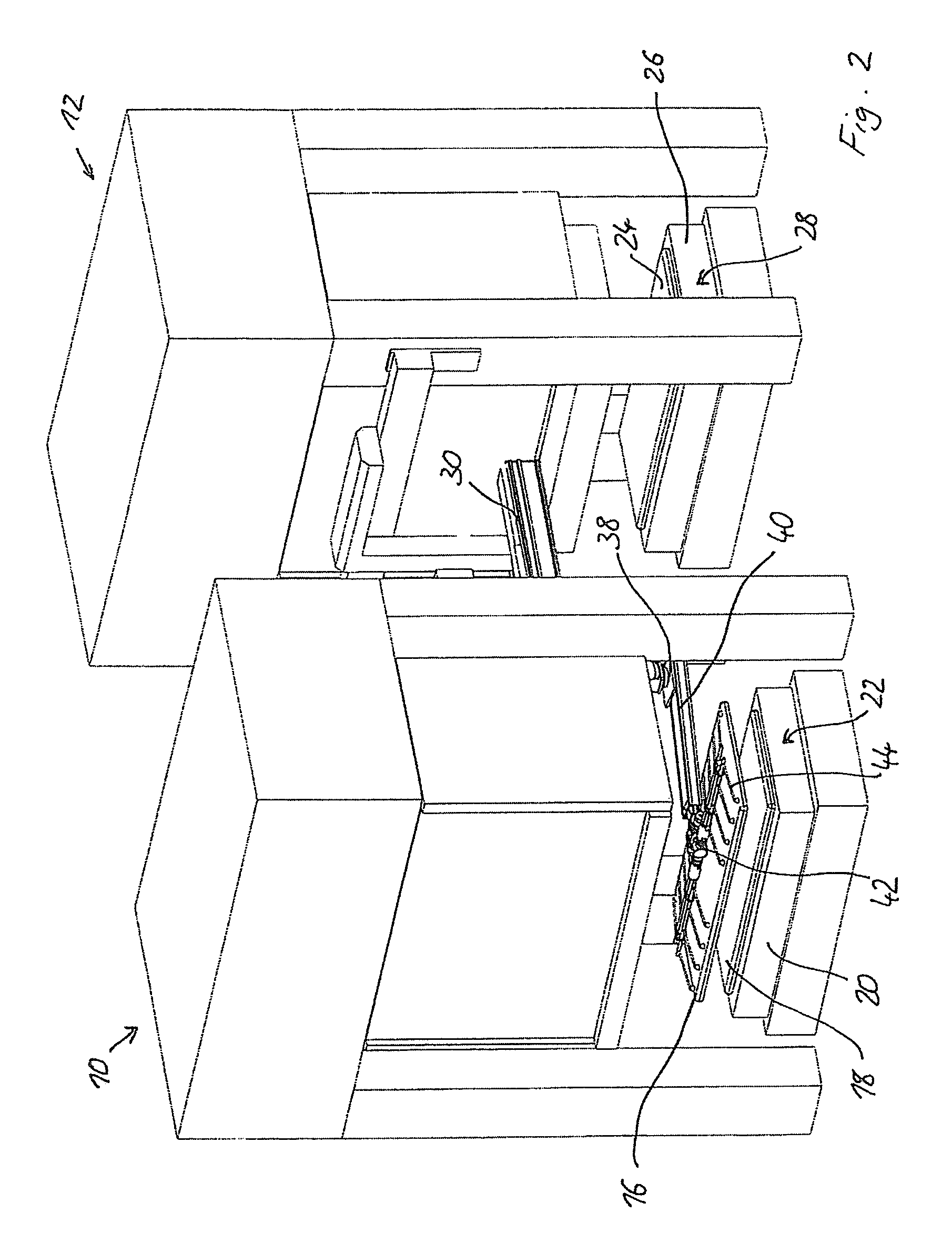
[0027]FIG. 1 shows two subsequent molding presses 10,12 within a molding press line in a schematic manner. Between the molding presses, a manipulator 14 according to the present invention is provided for transferring a workpiece 16 from a first press 10 into the subsequent second press 12. Press 10 comprises a taking position 18 on top of the lower half 20 of a press tool 22, while the second press 12 comprises a reception position 24 on top of the lower half 26 of its press tool 28. The manipulator 14 is provided for taking the workpiece 16 after the pressing operation within the first press 10 from the taking position 18 and to transfer it into the reception position 24 of the second press 12.

[0028]For this purpose the manipulator 14 comprises a horizontal beam 30 extending within the space between the two presses 10,12. At the beam 30, rails 32 are provided onto which a horizontal carriage 34 is movable between both ends of the beam 30. At the horizontal carriage 34, a vertically...


PUM


Abstract

A manipulator for transporting work pieces, especially between two subsequent molding presses of a press working line, including a moving mechanism allowing three dimensional movements on the path between the molding presses, a supplemental arm attached to the moving mechanism and connected to this moving mechanism via a support member that allows a swiveling movement of the supplemental arm around a vertical axis of the support member as well as a translation movement of the supplemental arm with respect to the support member, and a tool support provided at the outer end of a supplemental arm, the tool support being rotatable around a horizontal first axis and around a second axis perpendicular to the first axis, the tool support including a tool reception that is rotatable around a third axis perpendicular with respect to the second axis.

Description

BACKGROUND OF THE INVENTION[0001]The present invention refers to a manipulator for transferring work pieces, especially between two subsequent molding presses within a molding press line, comprising a moving mechanism for performing three dimensional movements on the path between the two molding presses.[0002]Manipulators are known in a large variety. Some of these manipulators comprise a pivotable manipulator arm with at least two limbs that are connected pivotable around a horizontal axis. By this pivoting or folding movement, the distance from the outer end of the manipulator arm to its support can be shortened or prolonged. Moreover, the height of the outer end of the manipulator arm can be changed by suitable pivoting movements of the two limbs of the arm around their horizontal pivot axis.[0003]When work pieces between two molding presses are transferred, it must be considered that there is not much space between the molding presses, and the space between the upper press tool ...

Claims


Application Information

Patent Timeline
IPC IPC(8): B65G47/91B21D43/05B21D43/10B25J15/00B25J9/02B65G1/133
CPCY10S901/40B21D43/05B25J15/0052Y10S901/16B21D43/105B25J9/023B65G47/91B25J15/0061
Inventor NAUMANN, BERNDWESSLING-SCHAFERS, MARKUS
Owner WILFRIED STROTHMANN MASCHENBAU & HANDHABUNGSTECHN
Why Eureka
Try Eureka