Differential pressure sensor system, aircraft equipped with a differential pressure sensor system and method for operating a differential pressure sensor system

Active Publication Date: 2017-11-23
AIRBUS OPERATIONS GMBH
View PDF0 Cites 2 Cited by
  • Summary
  • Abstract
  • Description
  • Claims
  • Application Information

AI Technical Summary

Benefits of technology

The invention is about a differential pressure sensor system that is designed to be more robust and less prone to errors. It also reduces the expenses associated with the sensor system. The system includes a shut-off device that prevents the sensor from being exposed to high cabin differential pressure, which increases its durability. The shut-off device can be operated in a self-contained manner, without needing to be connected to other components of the system. The system also includes a second port that can be connected to the aircraft cabin, which further prevents exposure to negative differential pressure. The control unit or biasing member can switch the shut-off device into its open position, even in a default condition. Overall, the differential pressure sensor system is designed to improve reliability and monitoring of the pressure between the aircraft cabin and the environment.

Problems solved by technology

Since an internal cabin pressure that is lower than the atmospheric ambient pressure, which is referred to as “underpressure,” is very dangerous for the structure of the aircraft, aircraft equipped with pressurizable cabins usually have protection mechanisms preventing the build-up of an underpressure.
If the door is then unlocked and opened in this overpressure state, it flies open in an uncontrolled, quick manner, thereby posing considerable hazard to both the aircraft structure and persons who are operating the door.

Method used


Image

  • Differential pressure sensor system, aircraft equipped with a differential pressure sensor system and method for operating a differential pressure sensor system
  • Differential pressure sensor system, aircraft equipped with a differential pressure sensor system and method for operating a differential pressure sensor system
  • Differential pressure sensor system, aircraft equipped with a differential pressure sensor system and method for operating a differential pressure sensor system

Examples


Embodiment Construction

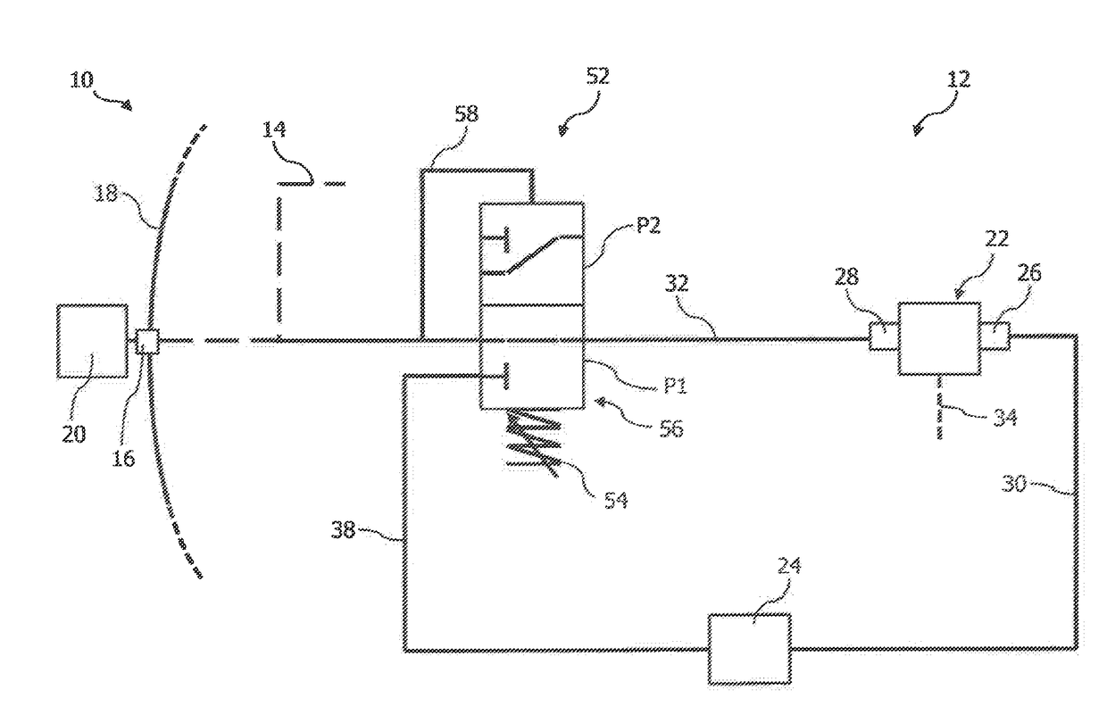
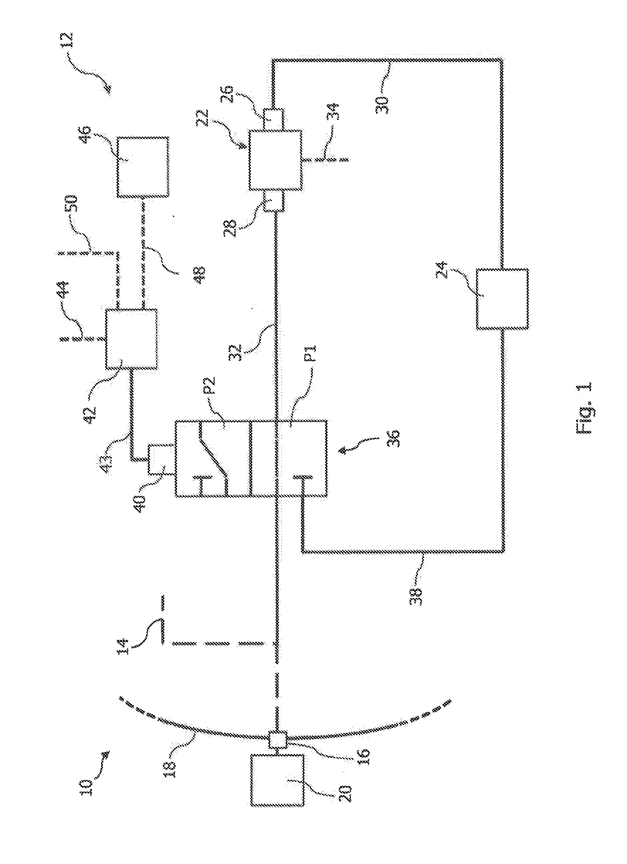
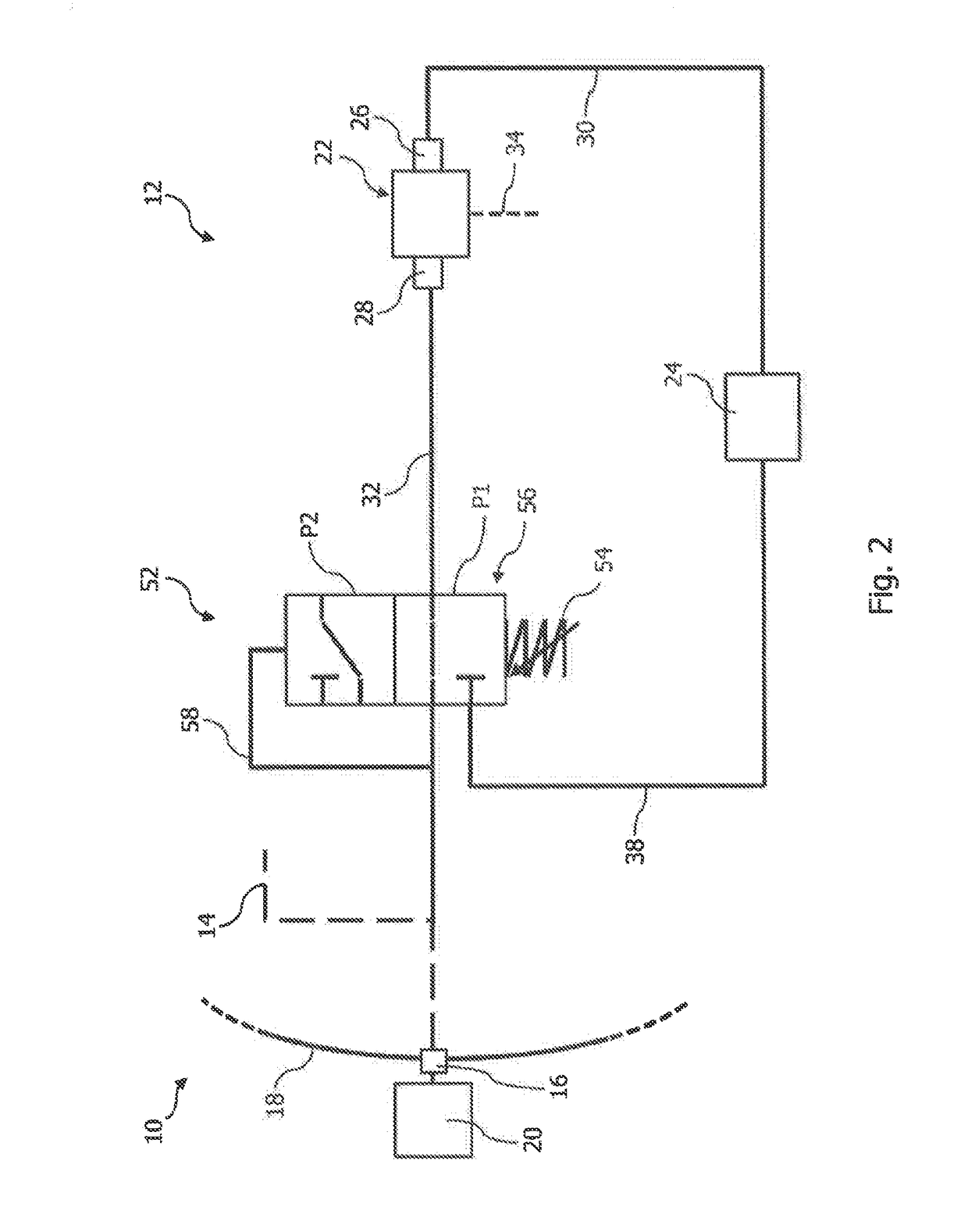
[0038]FIG. 1 depicts a schematic drawing of an area of an aircraft 10 in which a differential pressure sensor system 12 is installed. The aircraft 10 comprises a piping system 14 with an outside port 16 provided in an outer skin 18 of the aircraft 10, wherein the piping system 14 is connected to an aircraft environment 20 via the outside port 16.

[0039]The differential pressure sensor system 12 comprises a differential pressure sensor 22 for determining a differential pressure between a pressurizable aircraft cabin 24 of the aircraft 10 and the aircraft environment 20. The differential pressure sensor 22 may be used for a cabin differential pressure warning system or for any other system of the aircraft 10 which monitors a differential pressure between the pressurizable aircraft cabin 24 and the aircraft environment 20.

[0040]The differential pressure sensor 22 has a first port 26 and a second port 28. The first port 26 is connected to the pressurizable aircraft cabin 24 via a first l...


PUM


Abstract

A differential pressure sensor system for use in an aircraft comprises a differential pressure sensor for determining a differential pressure between a pressurizable aircraft cabin and an aircraft environment, the differential pressure sensor having a first port connectable to the pressurizable aircraft cabin via a first line and a second port connectable to the aircraft environment via a second line. A shut-off device of the differential pressure sensor system is arranged in the second line which is switchable between an open position in which it opens the second line, such that a pressure prevailing in the aircraft environment acts on the second port of the differential pressure sensor, and a shut-off position in which it closes the second line, such that the second port of the differential pressure sensor is shut off from the pressure prevailing in the aircraft environment.

Description

CROSS-REFERENCES TO RELATED APPLICATIONS[0001]This application claims the benefit of the European patent application No. 16 170 346.7 filed on May 19, 2016, the entire disclosures of which are incorporated herein by way of reference.BACKGROUND OF THE INVENTION[0002]The present invention relates to a differential pressure sensor system for use in an aircraft and an aircraft equipped with a differential pressure sensor system. Furthermore, the invention relates to a method for operating a differential pressure sensor system.[0003]Passenger aircraft which are operated at high flying attitudes are usually equipped with a pressurizable cabin which is accessible through lockable doors. In flight operation, since the atmospheric ambient pressure drops as the flying altitude increases, the pressurizable cabin ensures that an internal pressure thereof is kept essentially constant at an increased pressure level compared with the ambient pressure, i.e., the reduced atmospheric pressure at grea...

Claims


Application Information

Patent Timeline
IPC IPC(8): B64D45/00B64C25/34B64C25/00B64D13/02G01L19/00G01L13/00
CPCB64D45/00B64C25/34B64C25/001B64D2045/0085G01L13/00G01L19/0007B64D13/02B64D13/04
Inventor WAIGL, ILJAMAIL, MATIASKNIJNENBURG, THORSTEN
Owner AIRBUS OPERATIONS GMBH
Why Eureka
Try Eureka