
Method and systems for discharging energy from an electrical fault

a technology of electrical faults and methods, applied in the direction of emergency protective arrangements for limiting excess voltage/current, switchgear arrangements, and arrangements responsive to excess voltage, etc., can solve problems such as arc flashing, arc flashing can release significant energy, and damage to conductors and adjacent equipmen

Active Publication Date: 2014-12-30
ABB SPA
View PDF15 Cites 5 Cited by
  • Summary
  • Abstract
  • Description
  • Claims
  • Application Information

AI Technical Summary

Benefits of technology

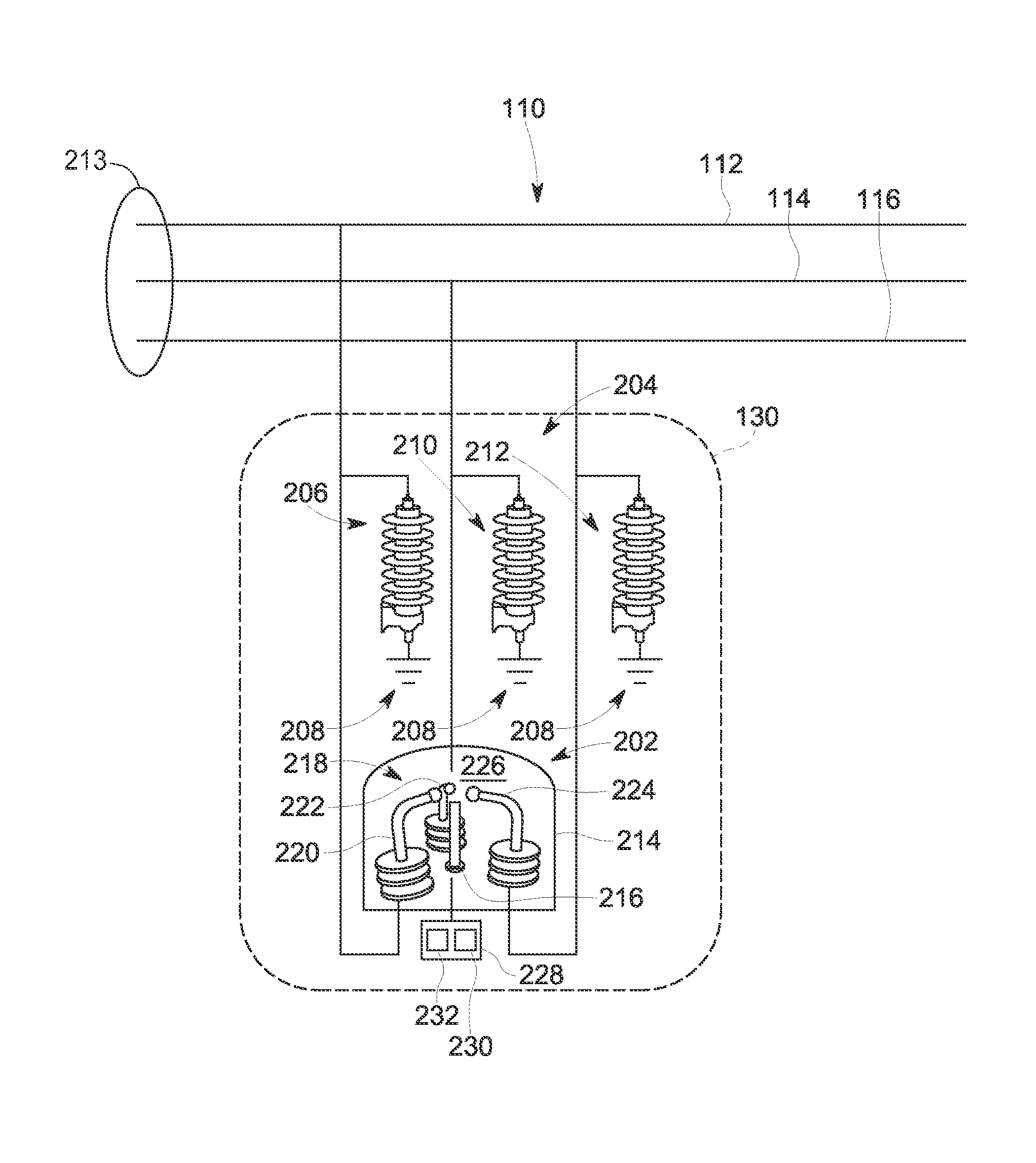
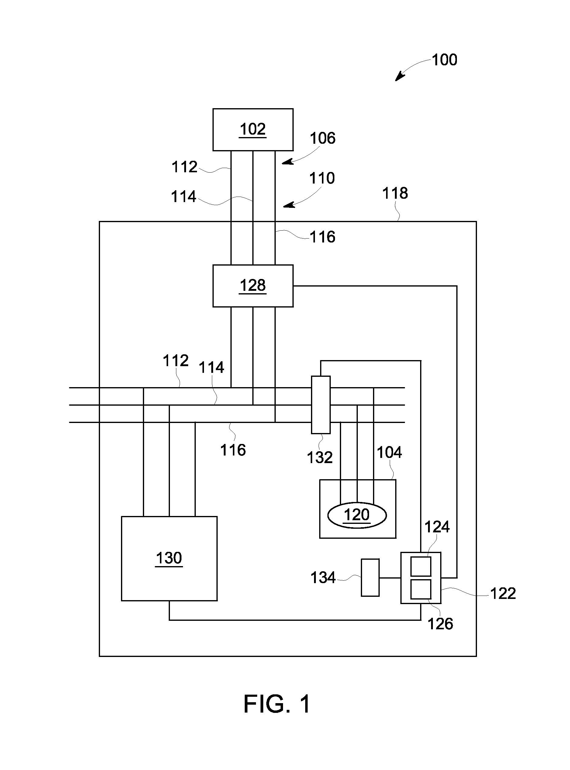
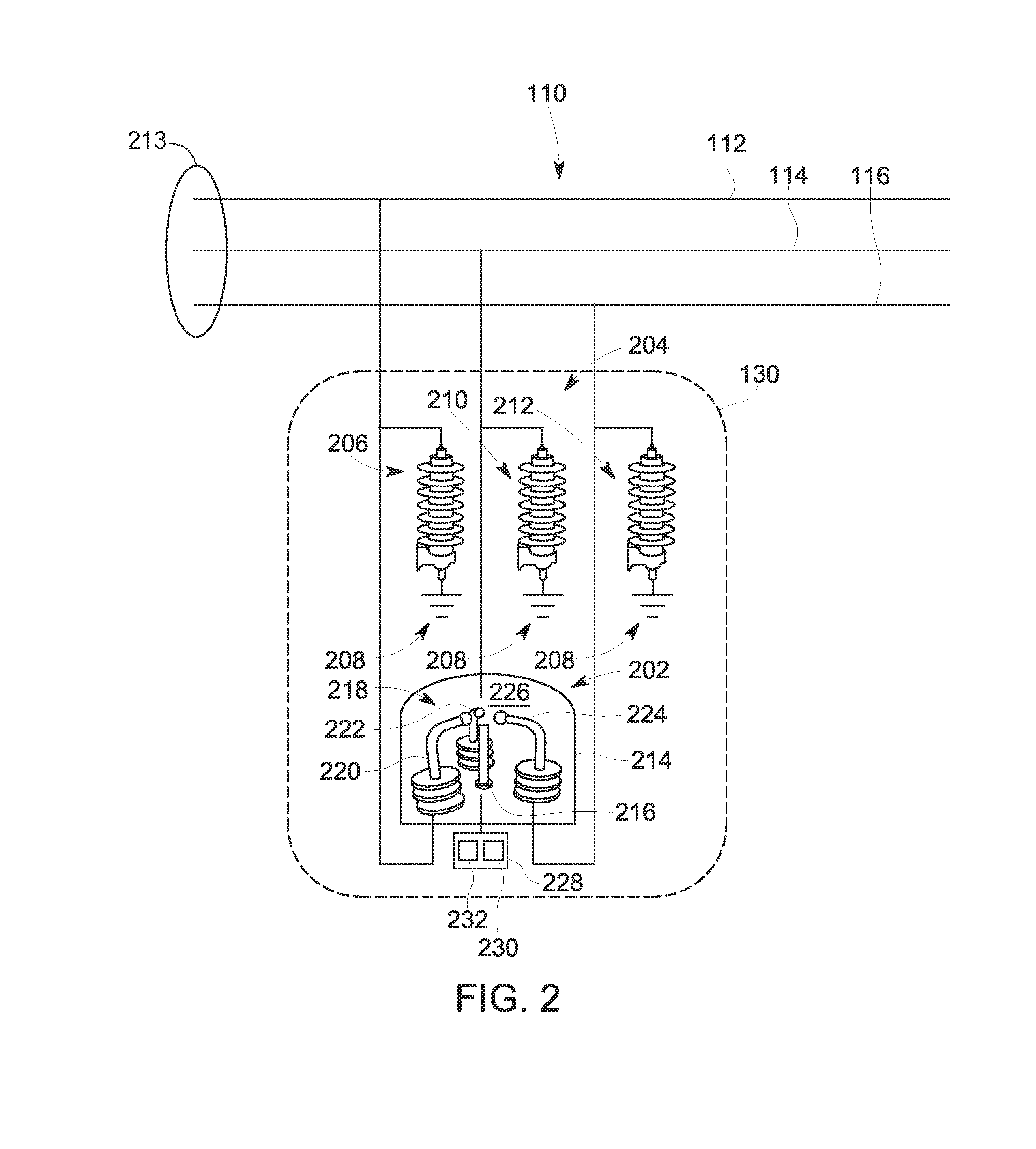
The patent text describes a system and method for protecting equipment in a power distribution system from electrical faults. The system includes a device called a mitigation device, which has a cavity with two electrodes inside. When a fault occurs, a voltage source applies a voltage to a plasma gun, which emits ablative plasma to form an electric arc between the electrodes and discharge energy from the fault. To prevent a second electrical arc, a voltage limiter device is placed on the first conductor to limit the voltage. The method includes detecting the fault and activating the mitigation device to discharge energy from the fault. The technical effect is to provide a system and method for protecting equipment from electrical faults in a power distribution system.

Problems solved by technology

However, if the conductors are positioned too closely together, or if a voltage between the conductors exceeds the insulative properties of the insulation between the conductors, an arc can occur.
In addition, an arc flash can release significant energy in the form of heat, intense light, pressure waves, and / or sound waves, sufficient to damage the conductors and adjacent equipment.
Standard circuit protection devices, such as fuses and circuit breakers, generally do not react quickly enough to mitigate an arc flash.
However, the intentional short circuit fault created using a crowbar may allow significant levels of current to flow through adjacent electrical equipment, thereby enabling damage to the equipment.

Method used


Image

  • Method and systems for discharging energy from an electrical fault
  • Method and systems for discharging energy from an electrical fault
  • Method and systems for discharging energy from an electrical fault

Examples


Embodiment Construction

[0013]Exemplary embodiments of a method and systems for use in discharging energy from an electrical fault are described herein. In an exemplary embodiment, an equipment protection system includes a controller, a current sensor, an optical sensor, and an arc mitigation system. The arc mitigation system includes a mitigation device and a voltage limiter device coupled to each conductor within the equipment protection system. If an electrical fault occurs, such as an arc flash event, the controller detects the fault using the current sensor and / or the optical sensor, for example. The controller transmits an activation signal to the mitigation device, and the mitigation device discharges energy from the electrical fault. More specifically, the mitigation device includes a plurality of electrodes and a plasma gun that emits ablative plasma into a gap defined between pairs of adjacent electrodes. The ablative plasma causes a low impedance path to be formed between the electrodes. The low...


PUM


Abstract

An electrical fault mitigation system includes a mitigation device including a containment chamber defining a cavity, a first electrode positioned within the cavity and coupled to a first conductor, and a second electrode positioned within the cavity and coupled to a second conductor. The mitigation device also includes a first voltage source, and a plasma gun positioned within the cavity and configured to emit ablative plasma using the first voltage source to discharge energy from an electrical fault. The system also includes a first voltage limiter device configured to limit a voltage of the first conductor from increasing above a predetermined threshold to prevent a second voltage source from generating a second electrical arc between the first electrode and the second electrode when the second voltage source applies a voltage across the first electrode and the second electrode.

Description

BACKGROUND OF THE INVENTION[0001]The present application relates generally to power systems and, more particularly, to a method and systems for use in discharging energy from an electrical fault.[0002]Known electric power circuits and switchgear generally have conductors that are separated by insulation, such as air, or gas or solid dielectrics. However, if the conductors are positioned too closely together, or if a voltage between the conductors exceeds the insulative properties of the insulation between the conductors, an arc can occur. The insulation between the conductors can become ionized, which makes the insulation conductive and enables arc formation.[0003]An arc flash is caused by a rapid release of energy due to a fault between two phase conductors, between a phase conductor and a neutral conductor, or between a phase conductor and a ground point. Arc flash temperatures can reach or exceed 20,000° C., which can vaporize the conductors and adjacent equipment. In addition, a...

Claims


Application Information

Patent Timeline
Patent Type & Authority Patents(United States)
IPC IPC(8): H02H7/00H02H3/00H02H9/02H02H3/08
CPCH02H9/06H01T2/02H02H1/0023H02B13/065
Inventor GANIREDDY, GOVARDHANPAPALLO, JR., THOMAS FREDERICHASOKAN, THANGAVELUBOHORI, ADNAN KUTUBUDDINRAORANE, DEEPAK RAJARAMPALVADI, SRINIVAS NAGA
Owner ABB SPA
Learn More