Microphone array system and method for sound acquisition

a microphone array and sound acquisition technology, applied in the field of microphone array systems, can solve the problems of limiting directivity, adverse effects on the quality of the acquired sound with the microphone, and linear microphone array geometries that are known to have limitations, etc., and achieve the effect of effectively adjusting the sound output volume of each sector

Active Publication Date: 2014-12-30
BIAMP SYST LLC
View PDF52 Cites 45 Cited by
  • Summary
  • Abstract
  • Description
  • Claims
  • Application Information

AI Technical Summary

Benefits of technology

[0023]It will be appreciated that using a set of beamformer weights that is applicable by rotation to any sector, e.g. any other sector, is made possible by employing a rotational' symmetrical microphone array.
[0033]Also, only a subset of sound source location points is used in each spatial reception sector during each processing cycle to perform sound source location. Further, only one sector point index entry of the sound source location point index is updated during a processing cycle. This reduces the processing time of the processing cycle that processes this information.
[0040]The selected weighting factor for each beamformer output signal may be determined as a function of the average value its pre-filter vector mask, and the selected weighting factor for each beamformer signal may be independently adjustable by a user via a user interface for effectively adjusting the sound output volume of each sector independently.
[0073]The selected weighting factor for each beamformer signal may be independently adjustable by a user for effectively adjusting the sound output volume of each sector independently.

Problems solved by technology

The quality of the acquired sound with the microphone is adversely affected by sound propagation losses from the users to the microphone.
Also, linear microphone array geometries that are known include limitations associated with the symmetry of their directivity patterns obtained from the microphone array.
However its maximum directivity lies in its plane which limits its directivity in relation to sound source locations falling outside the plane.

Method used


Image

  • Microphone array system and method for sound acquisition
  • Microphone array system and method for sound acquisition
  • Microphone array system and method for sound acquisition

Examples


Embodiment Construction

[0104]A microphone array system, in accordance with this invention, may manifest itself in a variety of forms. It will be convenient to hereinafter describe an embodiment of the invention in detail with reference to the accompanying drawings. The purpose of providing this detailed description is to instruct persons having an interest in the subject matter of the invention how to carry the invention into practical effect. However it is to be clearly understood that the specific nature of this detailed description does not supersede the generality of the preceding broad description. In the drawings:

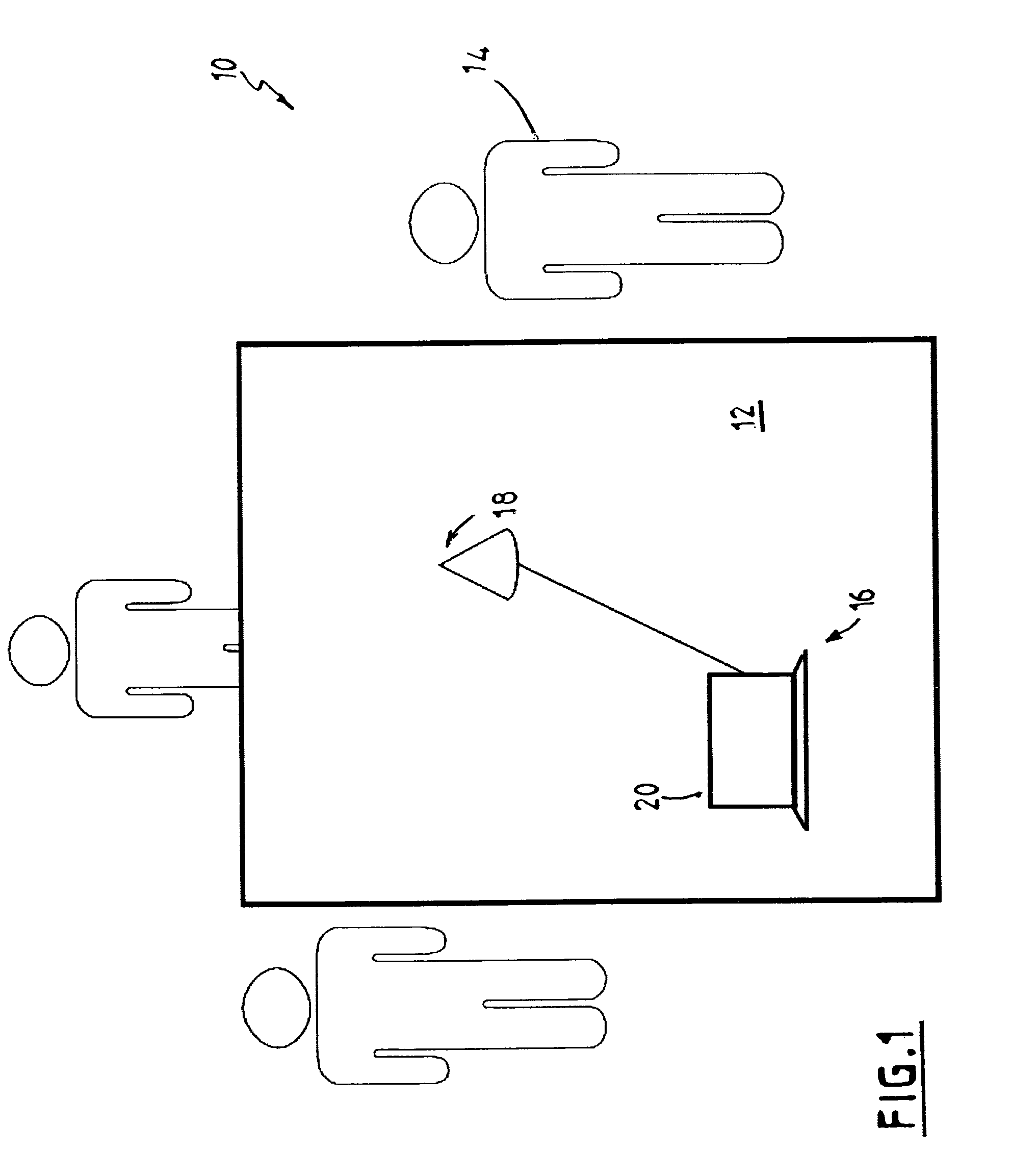
[0105]FIG. 1 shows schematically a meeting room in which users meet around a table, and a microphone array system, in accordance with the invention, in use, with a microphone array mounted on the table top;

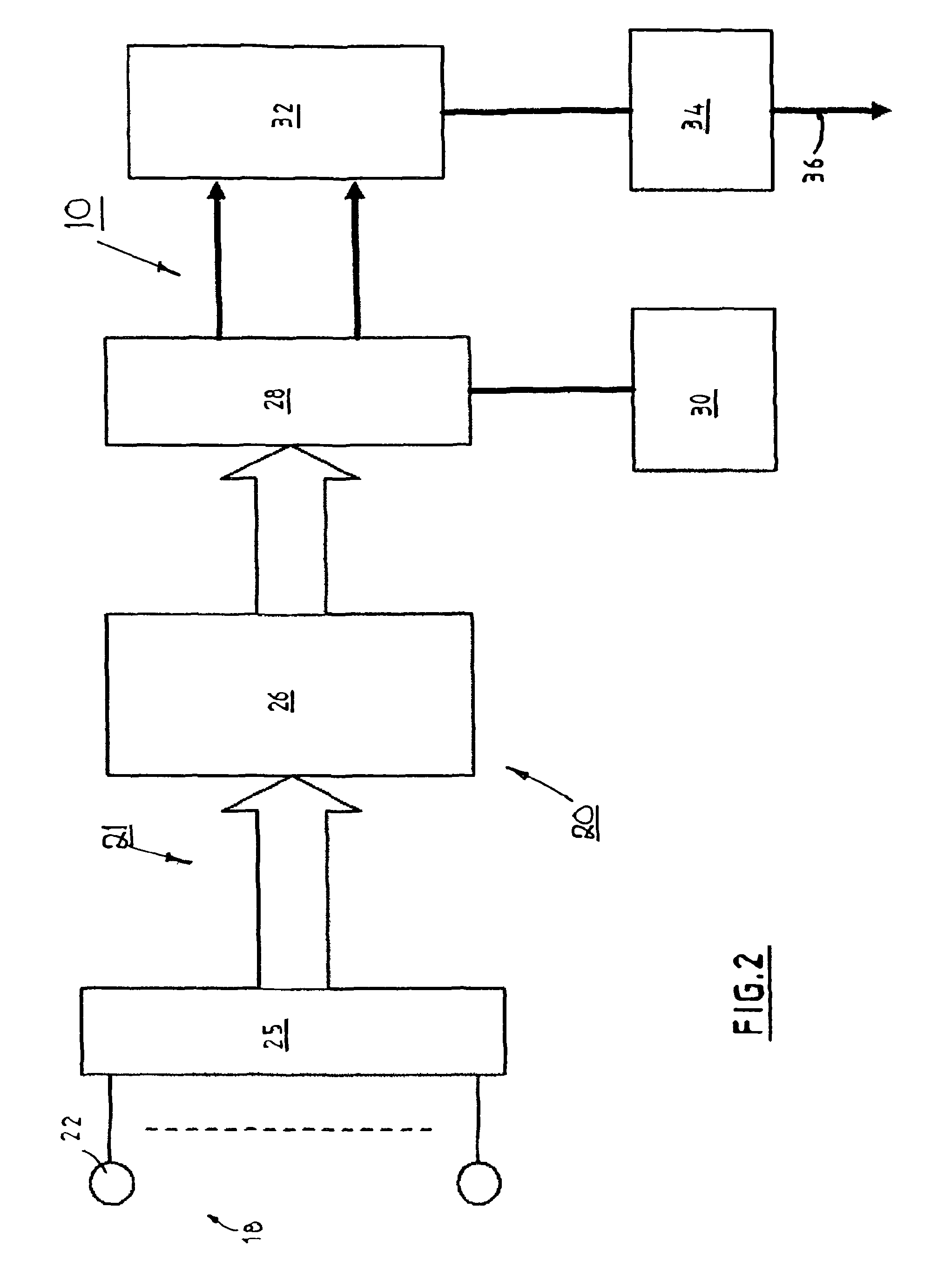
[0106]FIG. 2 shows a functional block diagram of the microphone array system in FIG. 1;

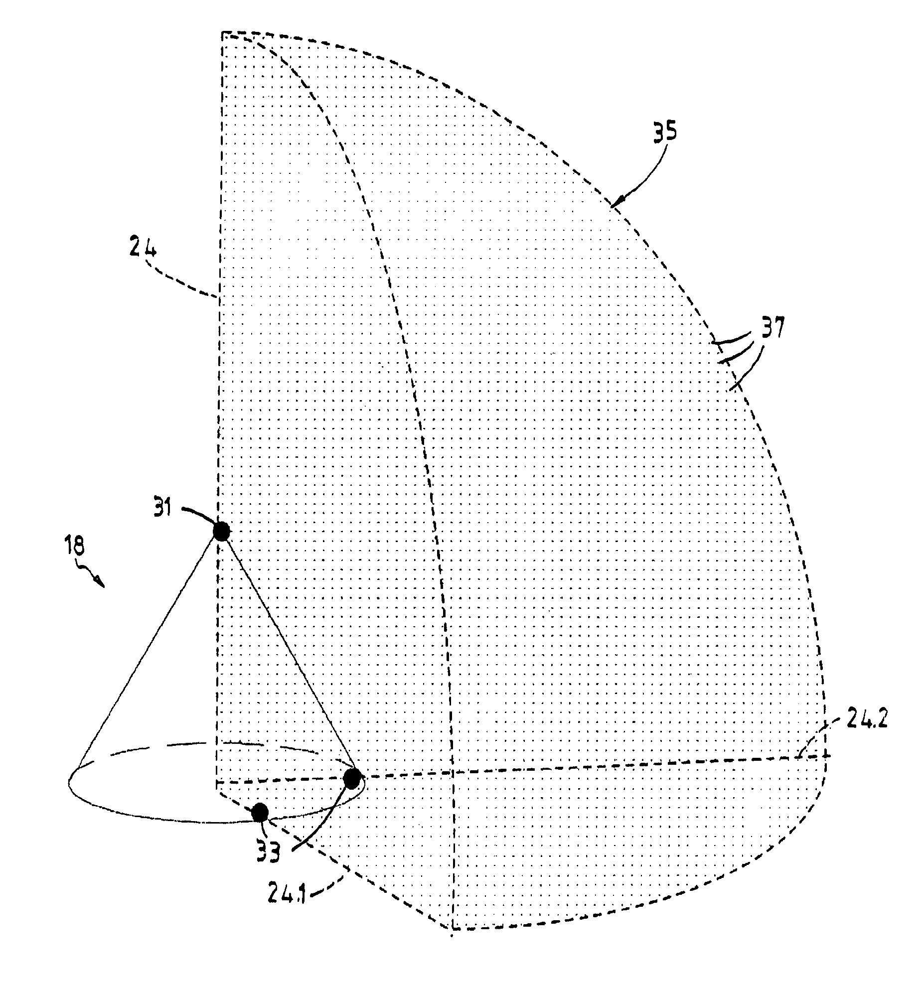
[0107]FIGS. 3A and 3B show schematically a three-dimensional view and a top view respectively of an ...


PUM


Abstract

A microphone array system (16) for sound acquisition from multiple sound sources in a reception space surrounding a microphone array (18) that is interfaced with a beamformer module (28) is disclosed. The microphone array (18) includes microphone transducers (22) that are arranged relative to each other in N-fold rotationally symmetry, and the beamformer includes beamformer weights that are associated with one of a plurality of spatial reception sectors corresponding to the N-fold rotational symmetry of the microphone array (18). Microphone indexes of the microphone transducers (18) are arithmetically displaceable angularly about the vertical axis during a process cycle, so that a same set of beamformer weights is used selectively for calculating a beamformer output signal associated with any one of the spatial reception sectors. A sound source location module (30) is also disclosed that includes a modified steered power response sound source location method. A post filter module (32) for a microphone array system is also disclosed.

Description

FIELD OF THE INVENTION[0001]This invention relates to a microphone array system and a method for sound acquisition from a plurality of sound sources in a reception space. The invention extends to a computer program product including computer readable instructions, which when executed by a computer, cause the computer to perform the method.[0002]The invention further relates to a method for sound source location, and a method for filtering beamformer signals in a microphone array system. The invention extends to a microphone array for use with a microphone array system.[0003]This invention relates particularly but not exclusively to a microphone array system for use in speech acquisition from a plurality of users or speakers surrounding the microphone array in a reception space such as a room, e.g. seated around a table in the room. It will therefore be convenient to hereinafter describe the invention with reference to this example application. However it is to be clearly understood ...

Claims


Application Information

Patent Timeline
Patent Type & Authority Patents(United States)
IPC IPC(8): H04H60/04H04R3/00
CPCH04R3/005H04R2430/03
Inventor MCCOWAN, IAIN ALEXANDER
Owner BIAMP SYST LLC
Why Eureka
Try Eureka