Air discharging device for an aircraft double-flow turbine engine

a technology of air discharging device and turbine engine, which is applied in the direction of aircraft power plant components, climate sustainability, aircraft power plants, etc., can solve the problems of difficult to ensure the sealing between the mobile parts of the device, the power required to activate it is indeed relatively high, and the effect of effective mastery

Inactive Publication Date: 2015-01-06
AIRBUS OPERATIONS (SAS)
View PDF21 Cites 1 Cited by
  • Summary
  • Abstract
  • Description
  • Claims
  • Application Information

AI Technical Summary

Benefits of technology

[0011]The invention in particular aims to provide a simple, economical and effective solution to these problems, making it possible to avoid at least some of the aforementioned drawbacks.

Problems solved by technology

The power necessary to activate them is indeed relatively high, these devices do not allow effective mastery of the noise annoyance, and it is in general difficult to guarantee sealing between the mobile parts of these devices.
The dual function of thrust reverser and air discharging device, as well as the independence of the two pivoting valves, requires the use of actuating means, such as electric jacks, which are numerous and powerful, which is detrimental to both the cost and mass of these devices and leaves little room for any sound-proofing fittings which are, however, necessary to reduce the sound annoyances emitted by the turbine engines.
In addition to the aforementioned drawbacks, this type of device has increased risks of failure due to the high complexity of the mechanism for actuating the pivoting valves.
Due to the small thickness of these fins, this device does not allow satisfactory joint use of actuators and acoustic insulation fittings.
Furthermore, it is difficult to guarantee sealing between the fins.

Method used


Image

  • Air discharging device for an aircraft double-flow turbine engine
  • Air discharging device for an aircraft double-flow turbine engine
  • Air discharging device for an aircraft double-flow turbine engine

Examples


Embodiment Construction

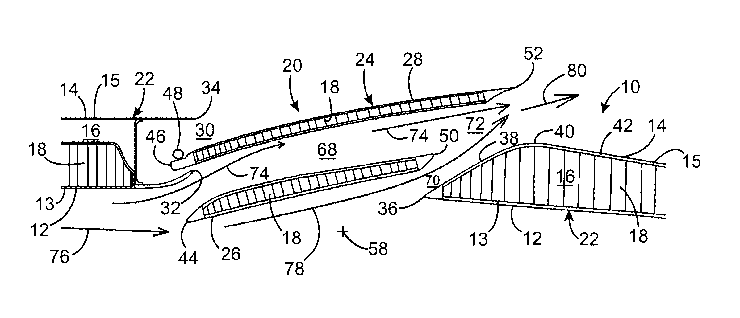
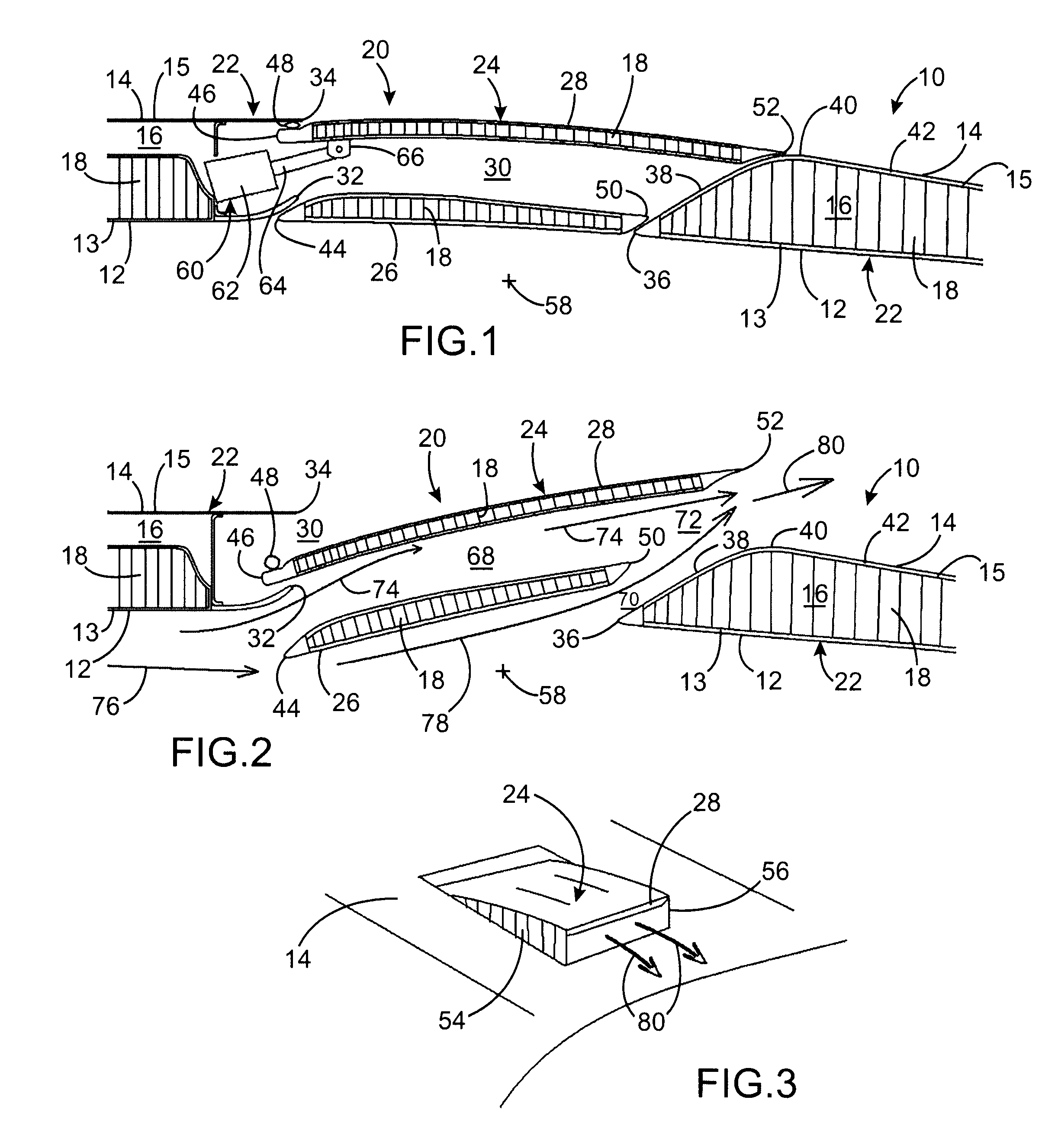
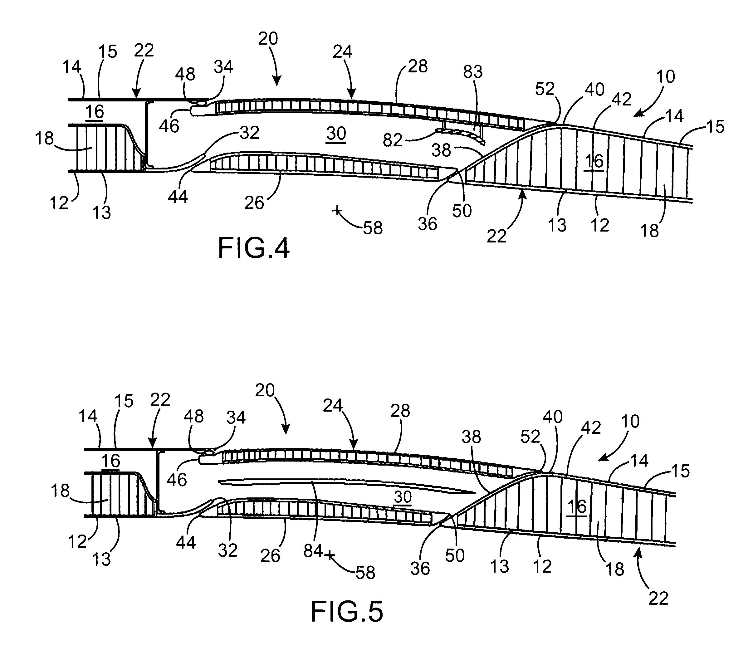
[0050]FIGS. 1 to 3 show part of an annular thrust reverser cowl 10 that is part of the nacelle of an aircraft dual-flow turbine engine according to one preferred embodiment of the invention.

[0051]The annular cowl 10 has two coaxial annular surfaces, an internal one 12 that outwardly defines an annular flow space for the secondary flow of the turbine engine, and an external one 14 that fairs the turbine engine. These two surfaces are formed on separate coaxial walls, an internal one 13 and an external one 15, respectively, between which a space 16 is formed in which acoustic insulation fittings 18 are arranged, which can occupy all or part of the transverse expanse of the space 16.

[0052]FIG. 1 more particularly illustrates an air discharging device 20 intended to allow, on command, an evacuation of part of the secondary flow through the annular cowl 10, the latter being able to comprise a plurality of devices of this type, for example distributed in an annular row around an axis of r...


PUM


Abstract

An air discharging device (20) for an aircraft turbine engine, comprising at least one door (24) displaceable between an open and a closed position of a corresponding orifice (30) and comprising two valves (26, 28), which delimit between them a conduit (68) for guiding a portion (74) of the secondary flow (76) outwards in the downstream direction, and which are integral with each other and are hinged around a pivot axis (58), so that in said open position, the upstream end of said internal valve (26) protrudes from the inner side relative to the internal surface (12), the downstream end of said external valve (28) protrudes from the external side relative to the external surface (14), and said internal valve (26) is spaced away from the fixed structure (22) so that an air passage exists downstream of said internal valve (26), between the latter and said fixed structure (22).

Description

TECHNICAL FIELD[0001]The present invention relates to an air discharging device for an aircraft double-flow turbine engine, of the type that can be incorporated into a turbine engine nacelle to allow, on command, a discharge of the secondary flow from the turbine engine, i.e. an increase in the output section of said secondary flow, by allowing part of said flow to escape through said device.[0002]Air discharging devices of this type make it possible to increase the operating stability of the fan of turbine engines that are equipped with them, to facilitate changes in the speed of rotation of said fan, and correlatively to decrease the noise annoyance due to the fan, to more correctly size the latter and to reduce the fuel consumption of said turbine engines.BACKGROUND OF THE INVENTION[0003]Air discharging devices for aircraft double-flow turbine engines of the known type can be placed in two main categories:[0004]a first category for devices that use a translation, along the axis o...

Claims


Application Information

Patent Timeline
Patent Type & Authority Patents(United States)
IPC IPC(8): F02K3/075F02K1/12B64D29/00F02K1/70F02K1/82
CPCF02K1/70B64D29/00F02K1/12F02K1/827Y02T50/671Y02T50/60
Inventor BULIN, GUILLAUMESURPLY, THIERRY
Owner AIRBUS OPERATIONS (SAS)
Why Eureka
Try Eureka