Assembly of stent grafts with diameter reducing ties

a technology of stent grafts and diameter reduction, applied in the field of stent grafts, can solve the problems of vessel wall relaxation, complicated positioning, and sizing errors

Active Publication Date: 2015-01-06
COOK MEDICAL TECH LLC
View PDF11 Cites 20 Cited by
  • Summary
  • Abstract
  • Description
  • Claims
  • Application Information

AI Technical Summary

Problems solved by technology

Positioning is complicated however because the diameter of a stent graft is deliberately made larger than the diameter into which it is to be placed to allow for accurate sealing against the vessel wall, possible errors in sizing and subsequent relaxation of the vessel wall.
Once released from a delivery device, a stent graft with self-expanding stents will take up apposition against the vessel wall and it will be difficult if not impossible to reposition it.
This can be dangerous if, for instance, renal arteries are occluded.
Sewing and positioning of such ties during manufacture can be difficult and time consuming.
Furthermore, errors in this process can have adverse effects.

Method used


Image

  • Assembly of stent grafts with diameter reducing ties
  • Assembly of stent grafts with diameter reducing ties
  • Assembly of stent grafts with diameter reducing ties

Examples


first embodiment

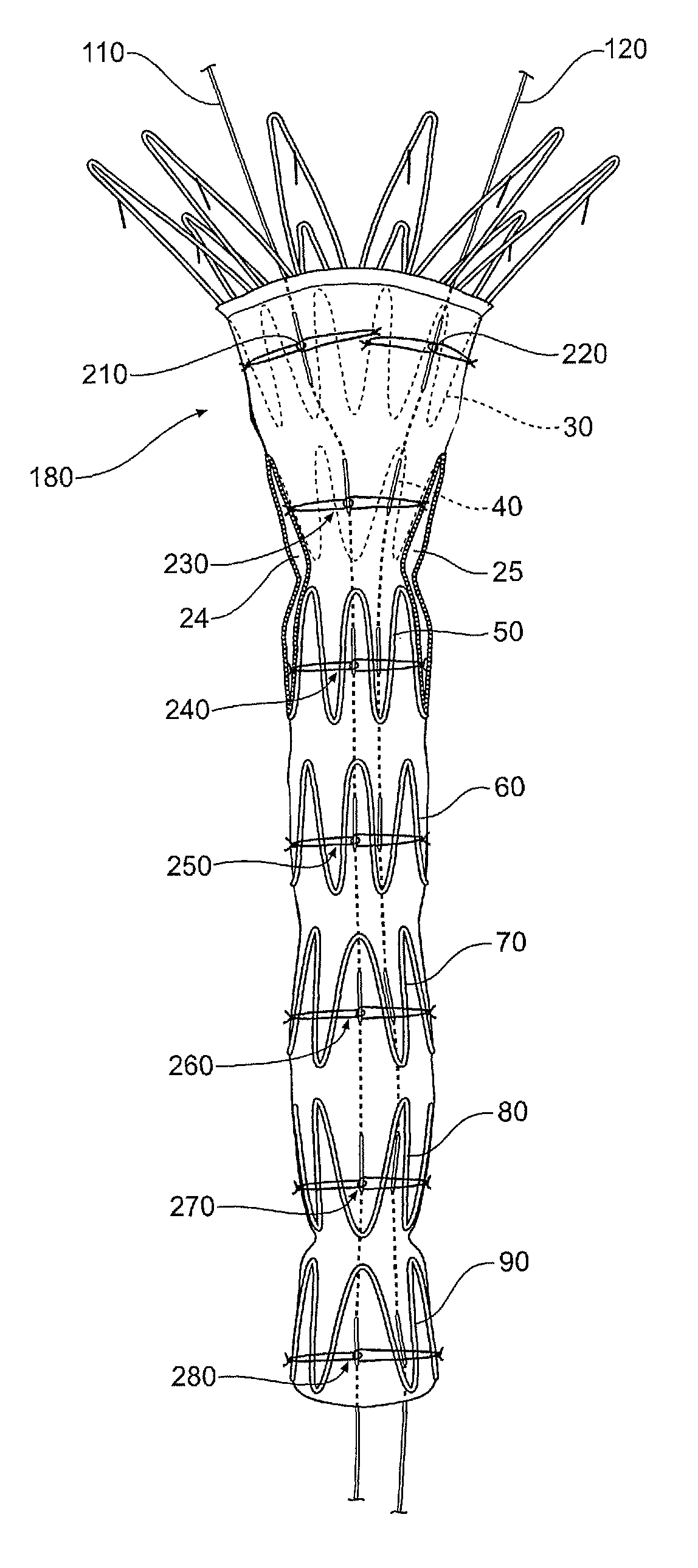
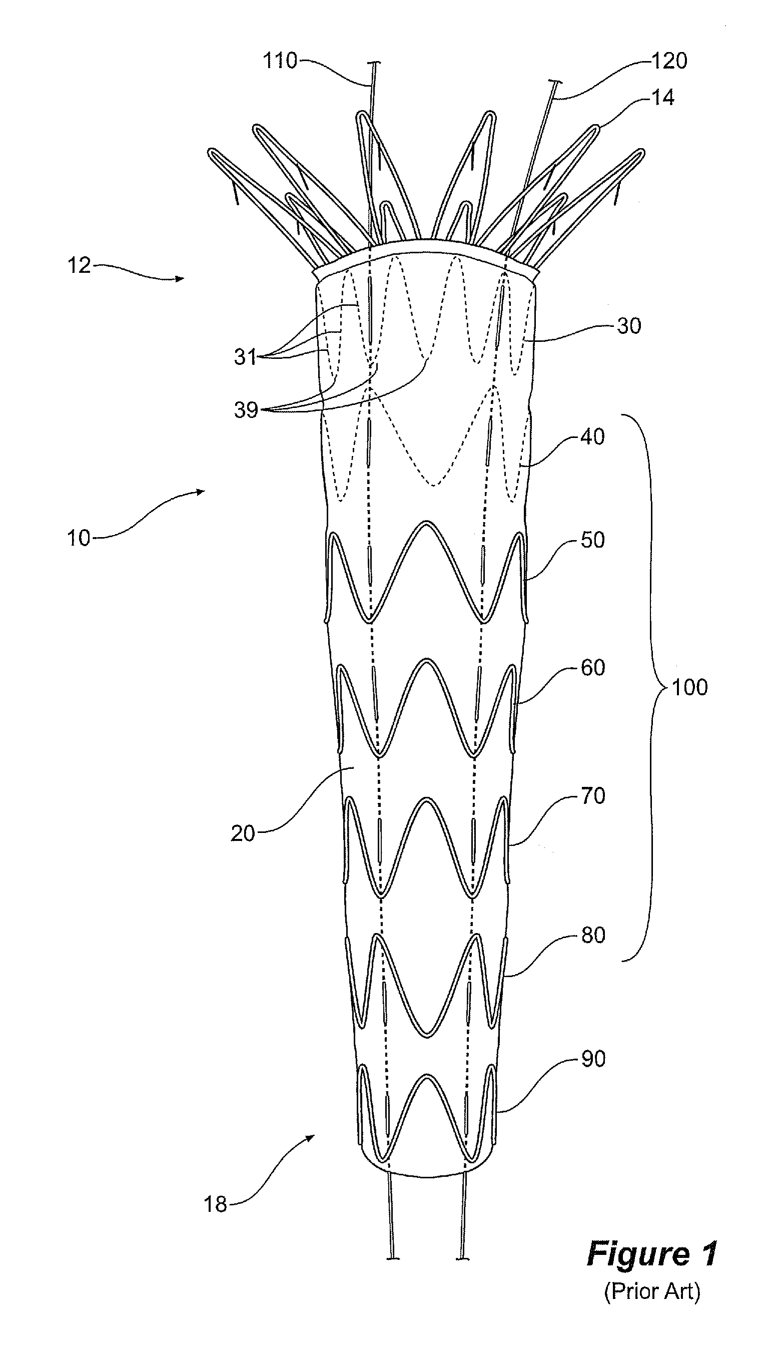
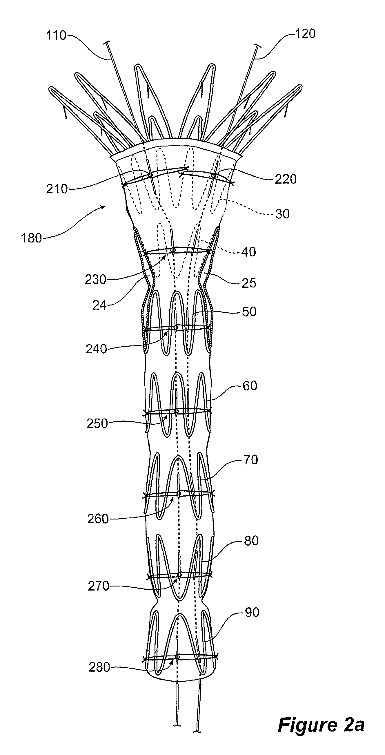
[0063]Referring now to FIGS. 2a, 2b and 3, a temporary diameter reduction constraint arrangement for a stent graft in combination with a stent graft according to the invention is shown. The stent graft 10 has a proximal end 12 and a distal end 18 and comprises a biocompatible graft material tube 20 of a selected diameter. It has two internal stents 30, 40 and a plurality of external stents 50, 60, 70, 80, 90 along the length of its tubular body. The internal stents 30, 40 are at the proximal end and act on a sealing zone also at the proximal end.

[0064]Fenestrations 24 and 25 are provided for allowing access to the renal arteries. This invention can facilitate matching the fenestrations 24 and 25 up with the renal arteries when the stent graft is deployed into an aorta. Methods of deployment of such a stent graft are described in PCT Patent Publication Number WO98 / 53761 entitled “A Prosthesis and a Method of Deploying a Prosthesis”. These features and other features disclosed in PCT ...

second embodiment

[0078]Having two wires close together, as is achieved with both the first and second embodiment of the invention as can be seen in FIGS. 3 and 5 respectively, gives the stent graft more support and helps the stent graft sit straighter. This makes it easier to load onto a deployment device.

[0079]FIG. 10 shows the stent graft of the second embodiment of the invention mounted onto a deployment device with a pusher catheter 150 at one end and a nose cone capsule 152 into which the proximally extending barbed stent 14 is received at the other end. At this stage a containing sheath has been withdrawn onto the pusher catheter so that the stent graft is partially expanded under the influence of self expanding stents but complete expansion has been prevented by the diameter reducing ties pairs 210, 220, 230, 240, 250, 260, 270 and 280.

[0080]The release wires 110 and 120 can be removed by the surgeon when (s)he no longer requires the diameter to be reduced. This can be when the stent graft is...


PUM

PropertyMeasurementUnit
biocompatibleaaaaaaaaaa
distanceaaaaaaaaaa
diameteraaaaaaaaaa

Abstract

A temporary diameter reduction constraint arrangement for a stent graft is disclosed. The arrangement comprises: primary and secondary release wires extending along the graft; a plurality of loops of thread, each loop engaged with either the primary or secondary wire and engaged around a portion of the graft circumferentially spaced away from its release wire, and drawn tight to reduce the diameter of the graft; an end constraint arrangement comprising four of the plurality of loops of thread arranged into a first and second pairs engaged with respective primary and secondary wires; and an intermediate constraint arrangement comprising a fifth and sixth of the plurality of loops of thread arranged into a third pair, the third pair engaged with the primary release wire, the primary release wire deviating towards the secondary release wire so as to locate the intermediate constraint arrangement substantially in-line with the end constraint arrangement.

Description

FIELD OF INVENTION[0001]This invention relates to a medical device and more particularly to a stent graft for mounting onto a deployment device for endovascular introduction.BACKGROUND OF THE INVENTION[0002]This invention will be particularly discussed in relation to stent grafts for placement into the thoracic abdominal aorta or into the abdominal aorta for the treatment of aneurysms. The invention, however, is not so restricted and may be applied to stent grafts for placement in any lumen of the human or animal body.[0003]The positioning of stent grafts is very important for a number of reasons including in many cases the need to avoid occlusion of branch arteries. Positioning is complicated however because the diameter of a stent graft is deliberately made larger than the diameter into which it is to be placed to allow for accurate sealing against the vessel wall, possible errors in sizing and subsequent relaxation of the vessel wall.[0004]Once released from a delivery device, a ...

Claims


Application Information

Patent Timeline
Patent Type & Authority Patents(United States)
IPC IPC(8): A61F2/07A61F2/06A61F2/95
CPCA61F2/07A61F2002/9511A61F2250/001A61F2002/061A61F2/852A61F2220/0075A61F2240/001Y10T29/49716
Inventor KING, CHANTELLE
Owner COOK MEDICAL TECH LLC
Why Eureka
Try Eureka