
Method for decorating surfaces

a surface and surface technology, applied in the direction of identification means, thermography, instruments, etc., can solve the problems of choosing optical machine-readable marking packs, which are not possible, and achieve the effect of improving the decoration of surfaces

Active Publication Date: 2015-01-13
LEONHARD KURZ STIFTUNG & CO KG
View PDF15 Cites 4 Cited by
  • Summary
  • Abstract
  • Description
  • Claims
  • Application Information

AI Technical Summary

Benefits of technology

The invention aims to improve the decoration of surfaces by allowing for individualized machine-readable optical markings to be applied. This creates a more customized, visually appealing appearance while also allowing for easier identification and tracking of the surface.

Problems solved by technology

On account of the printing processes that are used, which are optimized for high numbers of units, it is not possible in that case to choose the optical machine-readable marking pack-individually.

Method used


Image

  • Method for decorating surfaces
  • Method for decorating surfaces
  • Method for decorating surfaces

Examples


Embodiment Construction

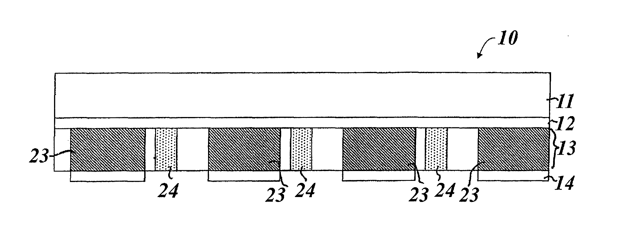
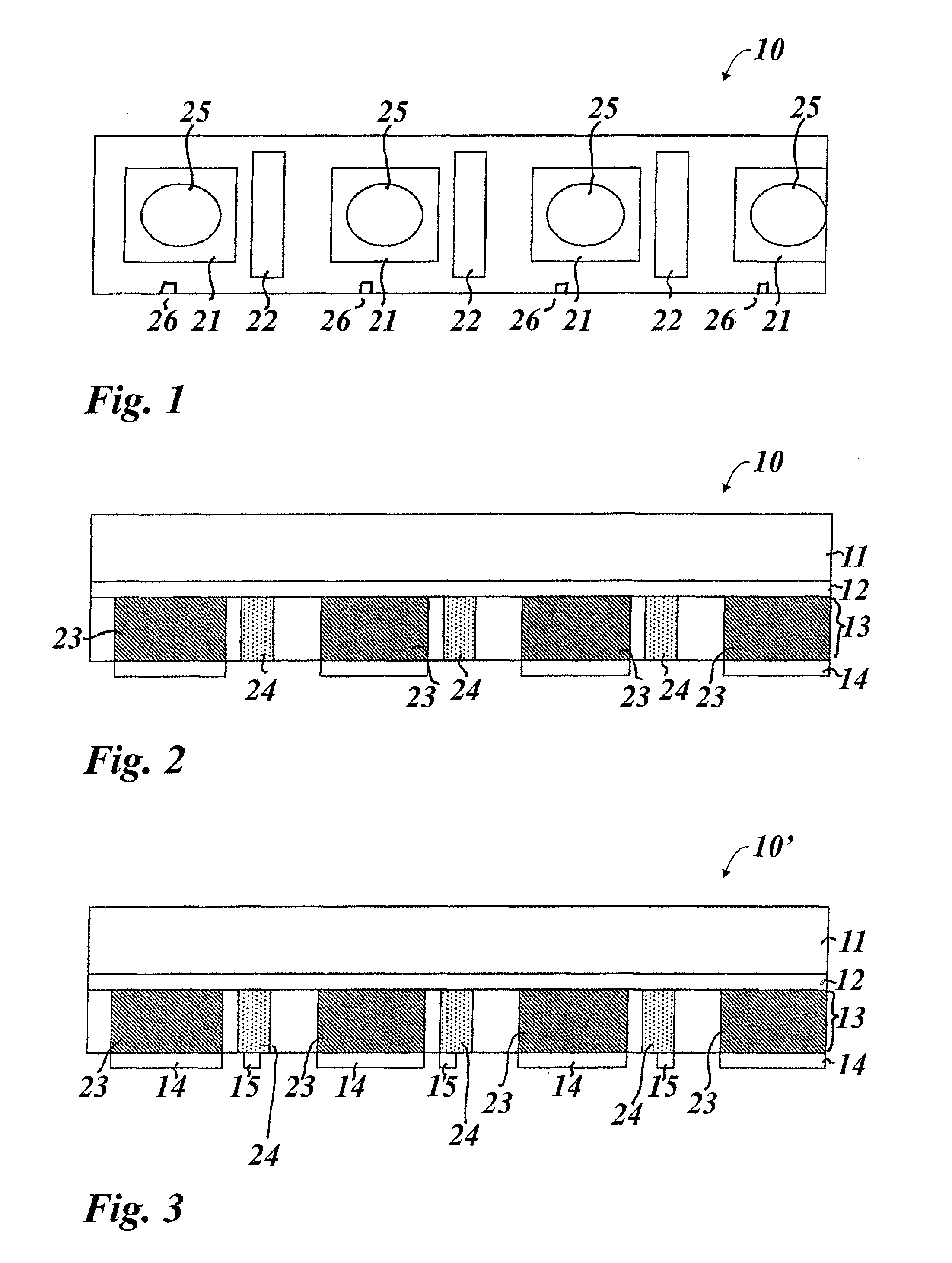
[0074]FIG. 1 and FIG. 2 show a detail from a transfer strip 10 with a number of area regions 21 and 22 and register marks 26. The transfer strip 10 has a strip-like shaping with a width preferably in the range from 5 mm to 50 mm, preferably from 15 mm to 30 mm, and a length which is preferably greater than the width of the transfer strip 10 by a factor of 500.

[0075]The transfer strip 10 has a strip-like backing film 11, a release layer 12, a decorative layer 13 and a partial adhesive layer 14.

[0076]The backing film 11 is preferably a film of plastic with a layer thickness of between 6 and 200 μm, more preferably between 12 and 36 μm. With preference, the backing film consists of PET, BOPP, PVC, PC or PP.

[0077]With preference, the release layer 12 has wax components, which have the effect that, when heated, in particular during a hot embossing operation, the bonding force imparted by the release layer between the backing film 11 and the decorative layer 13 is reduced, and thus the re...


PUM

PropertyMeasurementUnit
transparencyaaaaaaaaaa
widthaaaaaaaaaa
widthaaaaaaaaaa

Abstract

The invention relates to a method and a transfer strip for decorating surfaces, in particular for decorating outer packagings. A transfer strip comprising a strip-like backing film (11), a decorative layer (13) and a release layer (12) arranged between the decorative layer (13) and the backing film is provided. The decorative layer (13) has a multiplicity of identical optically variable decorative elements, which are arranged in first area regions, which are separate from one another and spaced apart from one another in the longitudinal direction of the transfer strip. The decorative layer (13) has second area regions, which are separate from one another and spaced apart from one another in the longitudinal direction of the transfer strip and in which the decorative layer (13) has one or more individualizable layers for providing respectively different machine-readable optical markings. A first area region or a subregion of a first area region and a second area region or a subregion of a second area region of the decorative layer (13) is respectively transferred to a surface to be decorated. The one or more individualizable layers of the respective second area region are individualized before or during the transfer, so that, in addition to one of the optically variable decorative elements, an individualized machine-readable optical marking is transferred from the transfer strip to the surface to be decorated.

Description

[0001]This application claims priority based on an International Application filed under the Patent Cooperation Treaty, PCT / EP2011 / 003126, filed on Jun. 24, 2011, and German Application No. DE 102010025278.6-45, filed on Jun. 28, 2010, and German Application No. DE 102010048817.8, filed on Oct. 20, 2010.BACKGROUND OF THE INVENTION[0002]The invention relates to a method for decorating surfaces, in particular for decorating outer packagings, and also to a transfer strip for decorating surfaces and to a packaging.[0003]It is known to provide outer packagings, for example outer packaging of foods, with a machine-readable optical marking, in particular a barcode. This machine-readable optical marking is usually printed onto the outer packaging by means of offset printing together with a surrounding decoration, which determines the decorative appearance of the outer packaging. On account of the printing processes that are used, which are optimized for high numbers of units, it is not poss...

Claims


Application Information

Patent Timeline
Patent Type & Authority Patents(United States)
IPC IPC(8): B41M5/382B44C1/17B41M5/40B23P19/04B44C1/10
CPCB44C1/1729B44F1/10B23P19/04B44C1/10B41M5/38214B41M5/405B41M2205/42B44C1/1733B42D25/405B42D25/425B42D25/36B42D25/328B42D25/364B42D25/47Y10T29/49826G09F3/00
Inventor LUTZ, NORBERTKURZ, WALTERBREHM, LUDWIGBEZOLD, HANS PETER
Owner LEONHARD KURZ STIFTUNG & CO KG
Learn More