Method for temporary or permanent disposal of nuclear waste

a technology of nuclear waste and temporary or permanent disposal, which is applied in the direction of solid waste disposal, radioactive decontamination, nuclear engineering, etc., can solve the problems of destroying life in the surrounding area, costing billions of dollars, and system costing many billions of dollars, and achieves the effect of prolonging safety

Active Publication Date: 2015-01-13
CRICHLOW HENRY
View PDF2 Cites 33 Cited by
  • Summary
  • Abstract
  • Description
  • Claims
  • Application Information

AI Technical Summary

Benefits of technology

[0013]Another object of the present invention is to provide a method of disposing of nuclear waste in underground rock formations which will provide prolonged safety from the nuclear waste and added protection to human health and the environment.
[0014]An additional object of the present invention is to provide a method of disposing of nuclear waste in underground rock formations which will provide protection in case of rupturing or leaking of the canister in which the waste is stored.
[0015]Another object of the present invention is to provide a method of disposing of nuclear waste in underground rock formations which will provide safe storage of the waste for at least 10,000 years.
[0016]A further object of the present invention is to provide a method of disposing of nuclear waste in underground rock formations which is impervious to surface effects such as flooding, glaciation or seismic interference.
[0018]An even further object of the present invention is to provide a method of disposing of nuclear waste in underground rock formations which will drill a primary vertical wellbore and secondary horizontal laterals extending therefrom.
[0022]A method of disposing nuclear waste in underground rock formations is disclosed by the present invention. The method includes the steps of selecting an area of land having a rock formation positioned therebelow. The rock formation must be of a depth able to prevent radioactive material placed therein from reaching the surface and must be at least a predetermined distance from active water sources and drilling a vertical wellbore from the surface of the selected area which extends into the underground rock formation. A primary horizontal lateral is drilled from the vertical wellbore whereby the surface of the horizontal lateral is defined by the underground rock formation. A steel casing is placed within the horizontal lateral and cemented in place by circulating cement in the annular space between the steel casing and the wall of the wellbore. Nuclear waste to be stored within the lateral is placed in a canister and the encapsulated nuclear waste is positioned within the primary horizontal lateral. The primary horizontal lateral is then filled with cementitious material to seal the encapsulated nuclear waste therein. Additional primary horizontal laterals can be drilled from the vertical wellbore and secondary and tertiary horizontal laterals can be drilled from the primary horizontal lateral. Additional layers of lead, cement and steel may be used to cover the laterals and shield the rock formation from any radiation leakage. Furthermore, front and end plugs may be positioned at either end of the laterals, retaining the canisters therein and providing added protection from leakage of any solid, liquid or gaseous material.

Problems solved by technology

The storage chambers are to be drilled approximately 1,000 feet into the mountain and can cost billions of dollars.
This method is dangerous as the canisters may rupture and pollute the ocean, killing life found in the surrounding area.
This system would cost many billions of dollars and thus is not very practical.
This method is not suitable as the salt caverns are located at quite shallow depths and in case there is a leakage, the water table may get contaminated.
This approach is not viable due to the great danger associated with disposing of the waste so close to the surface where leakage of the waste may do great harm to all life in the surrounding area.

Method used


Image

  • Method for temporary or permanent disposal of nuclear waste
  • Method for temporary or permanent disposal of nuclear waste
  • Method for temporary or permanent disposal of nuclear waste

Examples


Embodiment Construction

[0038]The present invention can be more fully understood by reading the following detailed description of some of the embodiments, with reference made to the accompanying drawings.

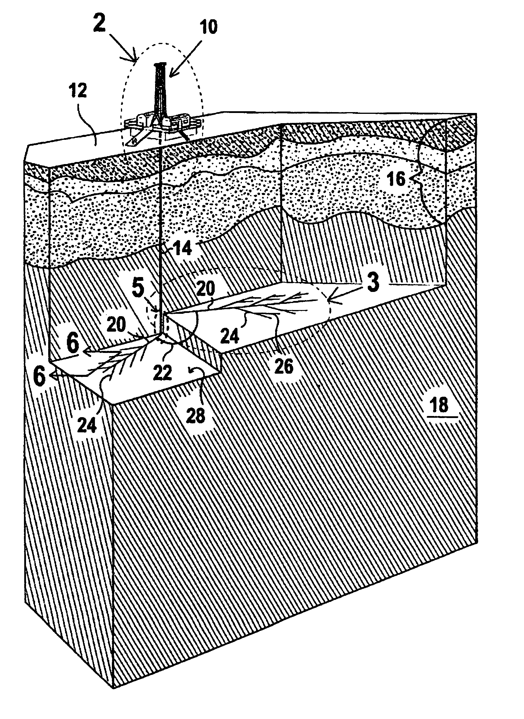
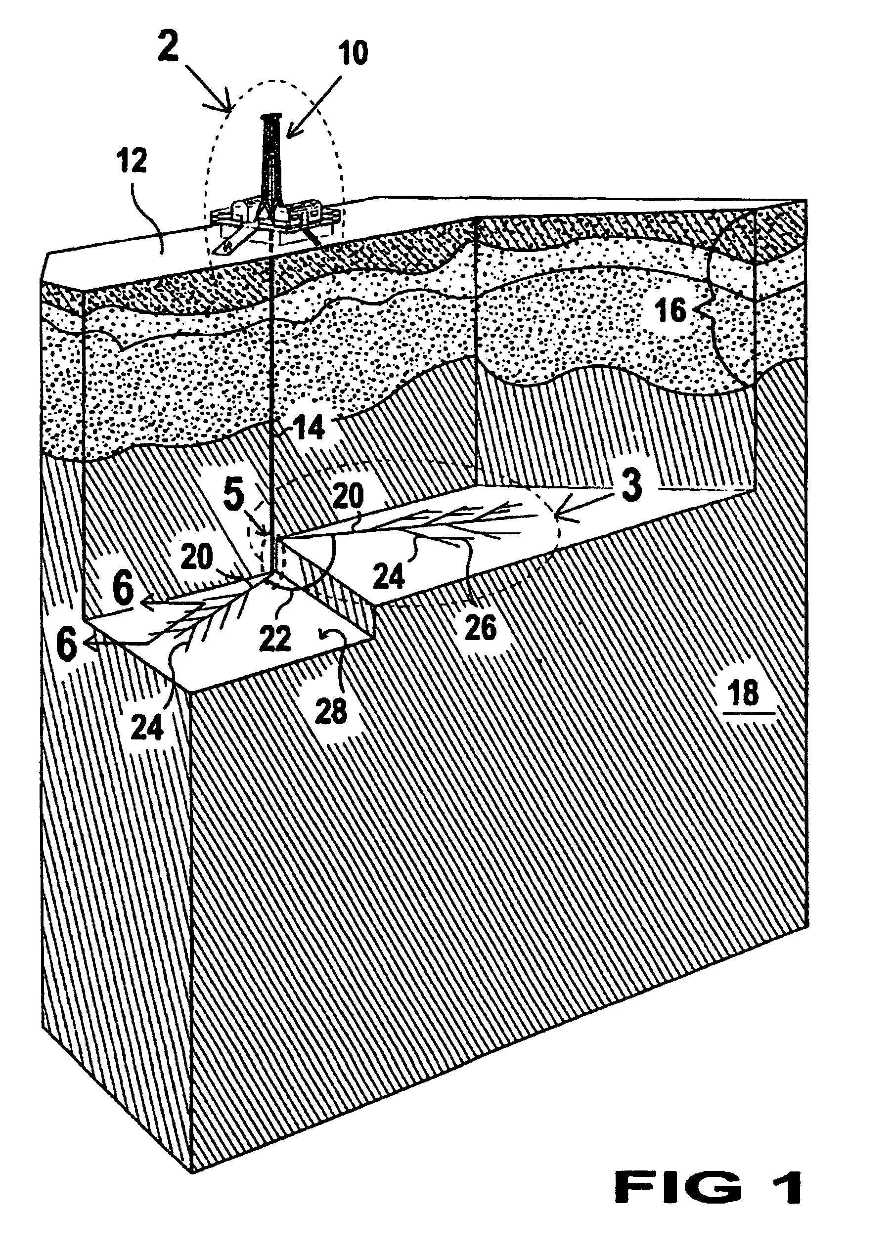
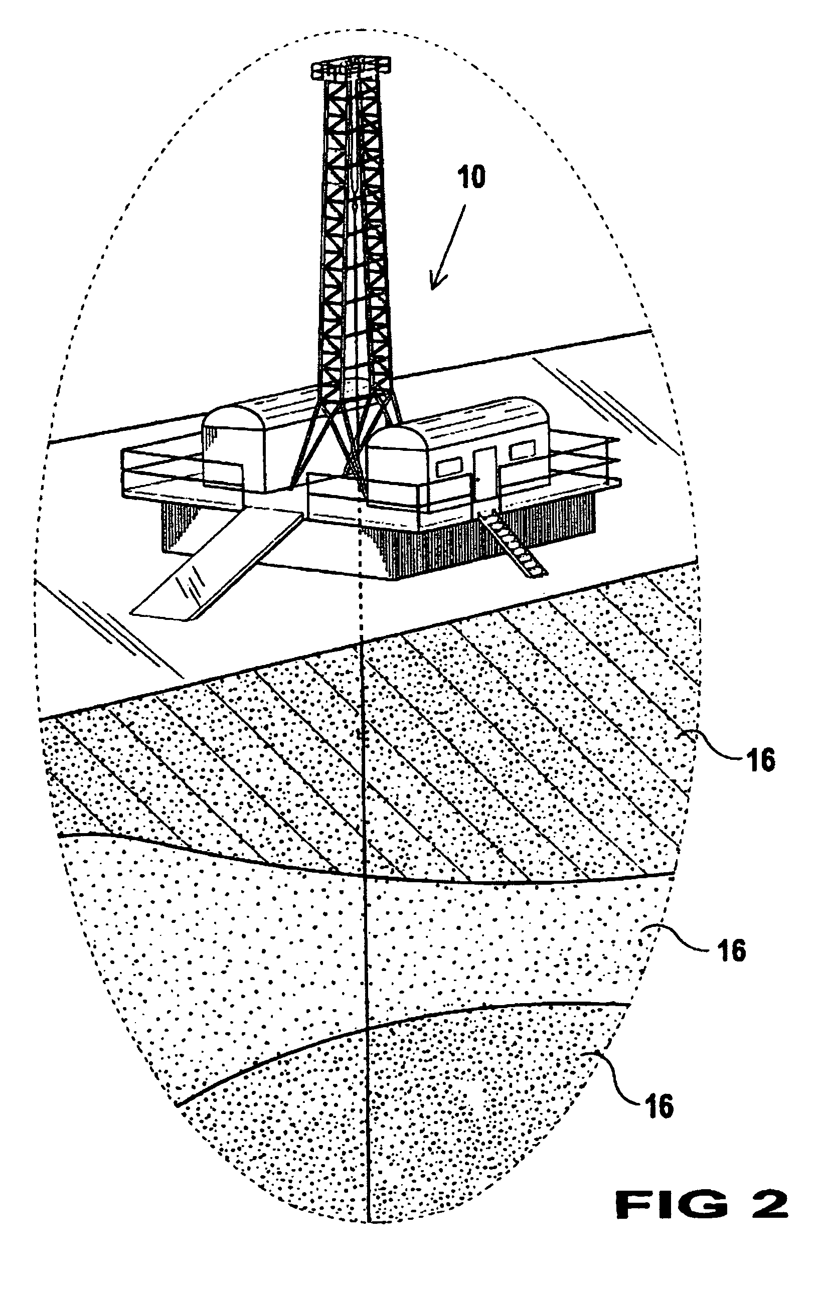
[0039]FIG. 1 shows a preferred embodiment of the equipment used and the results obtained when practicing the method of the present invention. A drilling rig 10 is positioned on an isolated surface 12 of the earth and is used to create a vertical wellbore 14 which will extend vertically into the earth's surface. The vertical distance is contemplated to be in the range of 5,000 feet to 25,000 feet. The vertical wellbore 14 extends through a plurality of layers of the earth's surface 16 and into a layer of rock 18 herein called the repository. The repository layer of rock 18 is a specially selected rock formation deep enough below the earth's surface to prevent radiation which may leak from reaching the surface. The selected rock formations have existed for billions of years as is evidenced by the chronologic...


PUM


Abstract

A method of disposing nuclear waste in underground rock formations is presented. The method includes the steps of selecting a land area having a rock formation positioned there-below of a depth able to prevent radioactive material placed therein from reaching the surface and drilling a vertical wellbore from the surface, to a depth ranging between 5,000 feet and 25,000 feet, into the underground rock formation or repository. A plurality of horizontal laterals or horizontal wellbores, ranging in length from 500 feet to 40,000 feet, are drilled from the vertical wellbore into the underground rock formation or repository. Nuclear waste to be stored within these laterals is encapsulated in a special waste canister and these nuclear waste canisters are positioned within the horizontal laterals wherein they are sealed to prevent loss and leakage. Means are also provided by which these canisters are adapted to allow retrievability of the canisters from the wellbore at a later date and to return the waste to the surface for use after retrieval.

Description

FIELD OF THE INVENTION[0001]The present invention relates generally to a system and method of disposing of nuclear waste. More particularly, the invention relates to disposing of nuclear waste temporarily or permanently in underground rock formations using multilateral boreholes.BACKGROUND[0002]Numerous methods for disposing of nuclear waste are provided in the art. For example, an existing disposal method for nuclear waste is to bury the waste in shallow vaults also known as deep vertical wells. This method places the waste in vertical silos drilled into a mountain by a tunnel boring machine. The storage chambers are to be drilled approximately 1,000 feet into the mountain and can cost billions of dollars.[0003]Another method proposed for disposing of nuclear waste is burial of the waste in suitable canisters in mud in the bottom of the ocean. This method is dangerous as the canisters may rupture and pollute the ocean, killing life found in the surrounding area.[0004]A further prop...

Claims


Application Information

Patent Timeline
Patent Type & Authority Patents(United States)
IPC IPC(8): G21F9/24
CPCG21F9/24G21F9/34
Inventor CRICHLOW, HENRY
Owner CRICHLOW HENRY
Why Eureka
Try Eureka