Image processing controller for performing image processing in cooperation with image forming apparatus, image forming system including image processing controller, method of controlling image forming system, and storage medium

a technology of image processing and image forming apparatus, which is applied in the direction of digital output to print units, climate sustainability, visual presentation, etc., can solve the problems of preventing the power supply of the image forming apparatus from being powered off, and the image forming apparatus frequently returning from the power saving state, so as to achieve the effect of wasting electric power

Inactive Publication Date: 2015-01-13
CANON KK
View PDF3 Cites 2 Cited by
  • Summary
  • Abstract
  • Description
  • Claims
  • Application Information

AI Technical Summary

Benefits of technology

[0009]The present invention provides a control technique which is capable of preventing an image forming apparatus from being caused to inefficiently return from a power saving state, and wastefully consuming electric power.
[0014]According to the present invention, when the image forming apparatus receives a job in the power saving state, the image processing controller determines whether or not to cause the image forming apparatus to return from the power saving state, based on the status of the image forming apparatus. If it is determined that there is no need to cause the image forming apparatus to return from the power saving state, the image processing controller stores the received job, and when the image forming apparatus returns from the power saving state, transmits the stored job to the image forming apparatus. In a case where it is determined that there is need to cause the image forming apparatus to return from the power saving state, the image processing controller transmits raster image data generated based on the received job to the image forming apparatus. This makes it possible to prevent the image forming apparatus from being caused to inefficiently shift from the power saving state, and wastefully consume electric power.

Problems solved by technology

In a case where the image forming apparatus is thus caused to return from the power saving state without taking the status of the image forming apparatus into account, this results in causing the image forming apparatus to frequently return from the power saving state.
Further, the input of a job sometimes causes the image forming apparatus to return from the power saving state in spite of being incapable of immediately executing print processing, and can hinder the image forming apparatus from being powered off according to a setting of automatic power off.

Method used


Image

  • Image processing controller for performing image processing in cooperation with image forming apparatus, image forming system including image processing controller, method of controlling image forming system, and storage medium
  • Image processing controller for performing image processing in cooperation with image forming apparatus, image forming system including image processing controller, method of controlling image forming system, and storage medium
  • Image processing controller for performing image processing in cooperation with image forming apparatus, image forming system including image processing controller, method of controlling image forming system, and storage medium

Examples


first embodiment

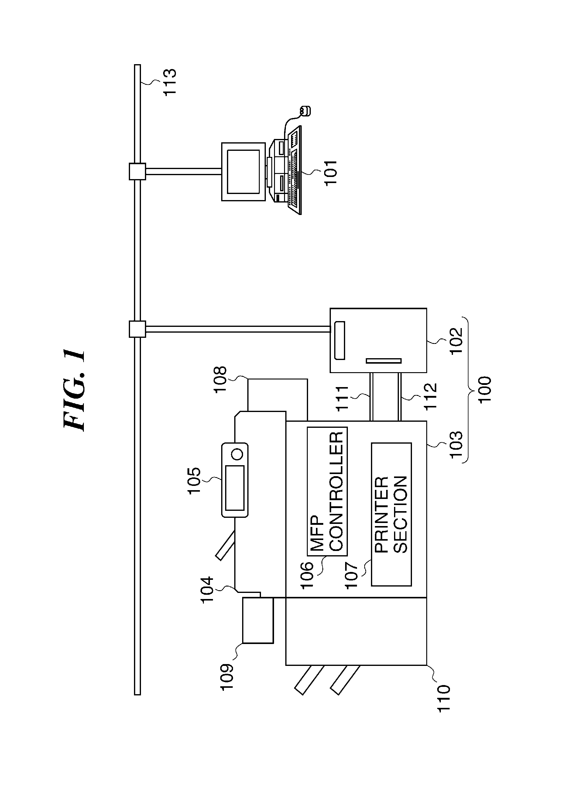
[0034]FIG. 1 is a block diagram showing the overall configuration of an image forming system including an image processing controller according to the present invention.

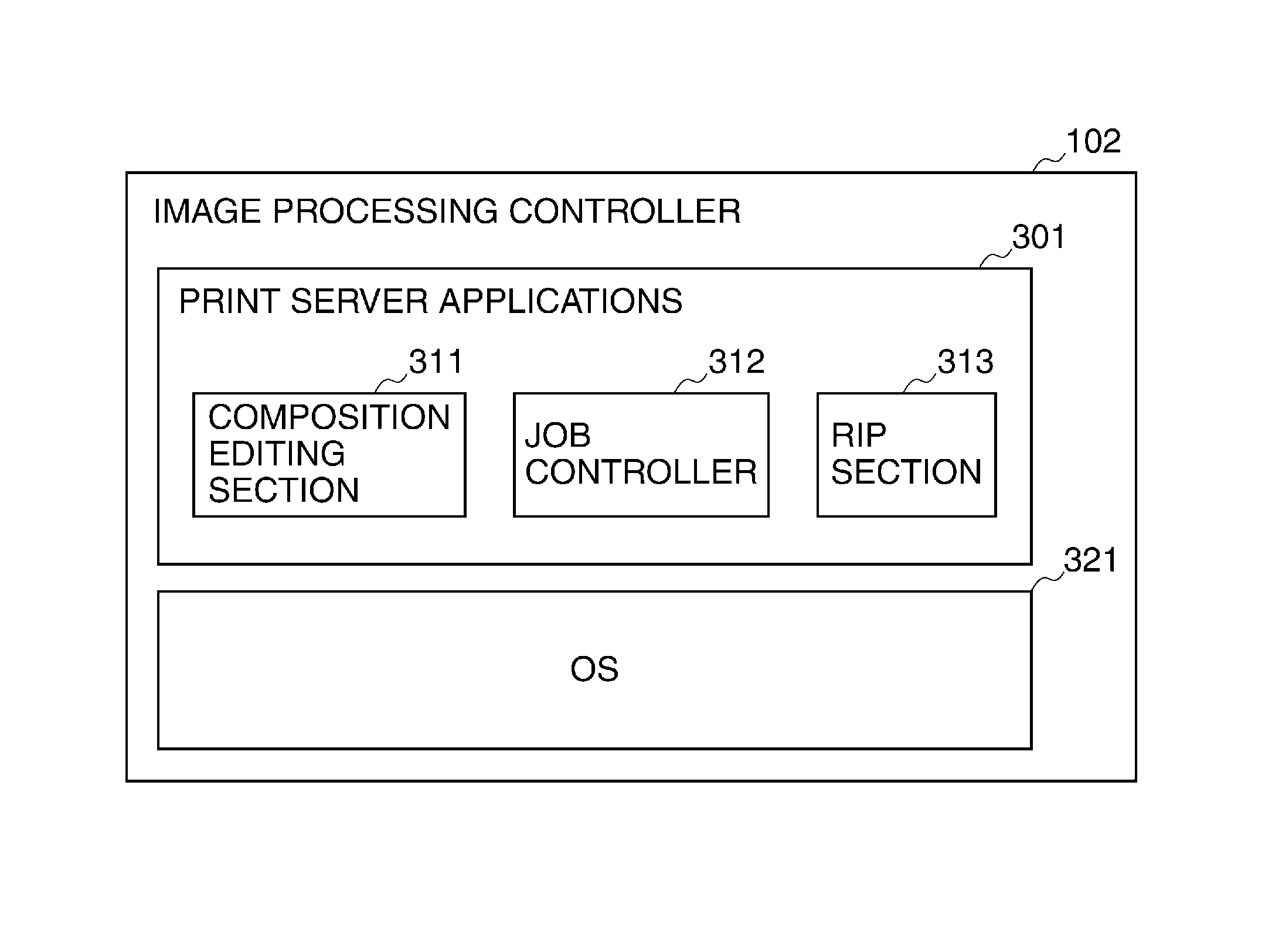
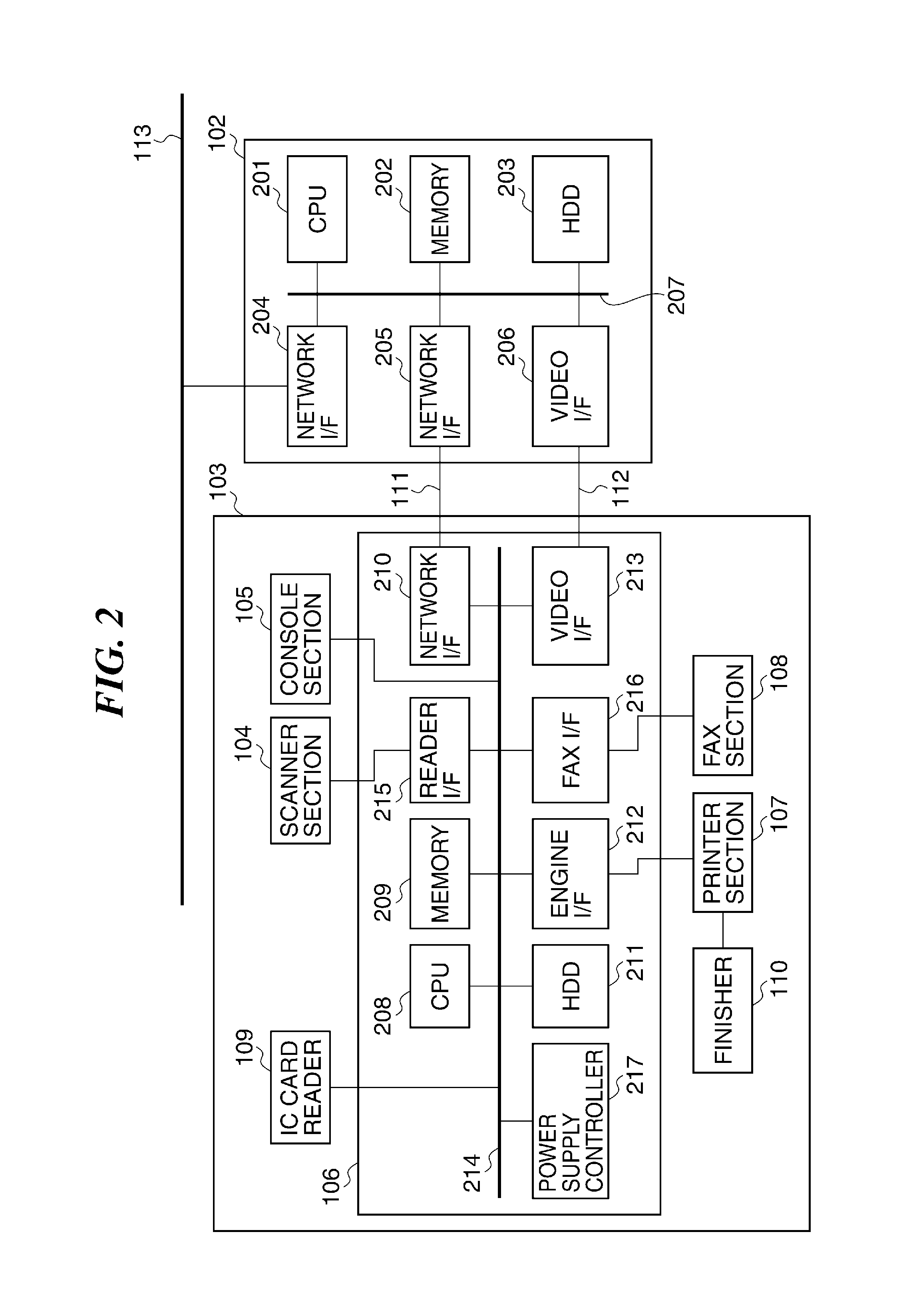
[0035]The image forming system, denoted by reference numeral 100, comprises the image processing controller, denoted by reference numeral 102, which performs image processing in cooperation with an image forming apparatus 103, and the image forming apparatus 103 which is an MFP (multifunction peripheral). The image forming system 100 is communicably connected to a client computer (PC) 101 connected to an Ethernet (registered trademark) cable 113. The PC 101 starts an application and issues a print instruction and the like to the image forming apparatus 103.

[0036]The PC 101 and the image processing controller 102 are communicably connected via the Ethernet (registered trademark) cable 113. The image processing controller 102 and the image forming apparatus 103 are connected via a control cable 111 and an image video c...

second embodiment

[0148]FIG. 16 is a view of an example of a job configuration screen displayed by an image processing controller for prompting a user to make a setting to a job as to whether the job can be subjected to postponed printing. Although the job configuration screen is assumed to be displayed during configuration of the job by a printer driver (not shown) or during configuration of the job by a job management application (not shown), this is not limitative. For example, the image processing controller 102 may be configured to have an ASP (Application Service Provider) function such that a job configuration screen is displayed on the PC 101 by the ASP function.

[0149]On the job configuration screen 1601, a dropdown list 1602 is displayed, and “print”, “postponed print”, or “wait” can be selected for an operation setting of a job to be placed in a print queue. When “print” is selected, the job is immediately placed in the print queue to start printing of the job. When “postponed print” is se...


PUM


Abstract

An image processing controller capable of preventing an image forming apparatus from being caused to return from a power saving state inefficiently, and wastefully consuming electric power. The controller acquires the status of the apparatus. When the apparatus has received a job in the power saving state, the controller determines whether or not to cause the apparatus to return from the power saving state based on the acquired status of the apparatus. The controller stores the job when there is no need to cause the apparatus to return from the power saving state, and transmits raster image data generated based the stored job to the apparatus when it has returned from the power saving state. When there is need to cause the apparatus to return from the power saving state, the controller transmits raster image data generated based on the received job to the apparatus.

Description

BACKGROUND OF THE INVENTION[0001]1. Field of the Invention[0002]The present invention relates to an image processing controller for performing image processing in cooperation with an image forming apparatus, an image forming system including the image processing controller, a method of controlling the image forming system, and a storage medium, and more particularly to a technique for controlling the image forming system in which the image forming apparatus capable of shifting to a power saving state and the image processing controller perform image processing in cooperation with each other.[0003]2. Description of the Related Art[0004]As a demand for power saving of apparatuses increases, an image forming apparatus has come to be widely used which is equipped with a function of shifting to a power saving state on condition that the image forming apparatus has not been operated for a predetermined time period. For example, when a predetermined time period or longer has elapsed after ...

Claims


Application Information

Patent Timeline
Patent Type & Authority Patents(United States)
IPC IPC(8): G06F3/12
CPCG06F3/1221G06F3/1229G06F3/126G06F3/1285H04N1/00896H04N1/00885Y02D10/00
Inventor MASUYAMA, YUKA
Owner CANON KK
Why Eureka
Try Eureka