
Baluster bracket assembly

Active Publication Date: 2015-01-20
SNEITH JAYME M
View PDF38 Cites 18 Cited by
  • Summary
  • Abstract
  • Description
  • Claims
  • Application Information

AI Technical Summary

Benefits of technology

The invention is a new way to attach balusters between handrails and baserails that doesn't require drilling big holes or using adhesive. It also reduces the cost and labor required for construction, repair, and replacement of railing systems. Its unique design solves the problem of inconvenience and unsightliness that current solutions present.

Problems solved by technology

This process is messy.
Other difficulties occur due to the ends of most balusters having a square cross-sectional shape, which forces the installer to drill holes large enough to receive the square end or chisel out a square hole.
Each of these solutions presents significant drawbacks.
Furthermore, if at any time the balusters become damaged or need to be replaced, the baluster must be cut out from the railing system and the ends and epoxy removed from the holes.
This process can likely damage both the handrail and the baserail causing additional problems.
Unfortunately, the hardware and methods presently available still require the drilling of large holes or utilize mechanical fasteners that are exposed, which can be unsightly and diminish the appearance of the otherwise decorative railing system.

Method used


Image

  • Baluster bracket assembly
  • Baluster bracket assembly
  • Baluster bracket assembly

Examples


Embodiment Construction

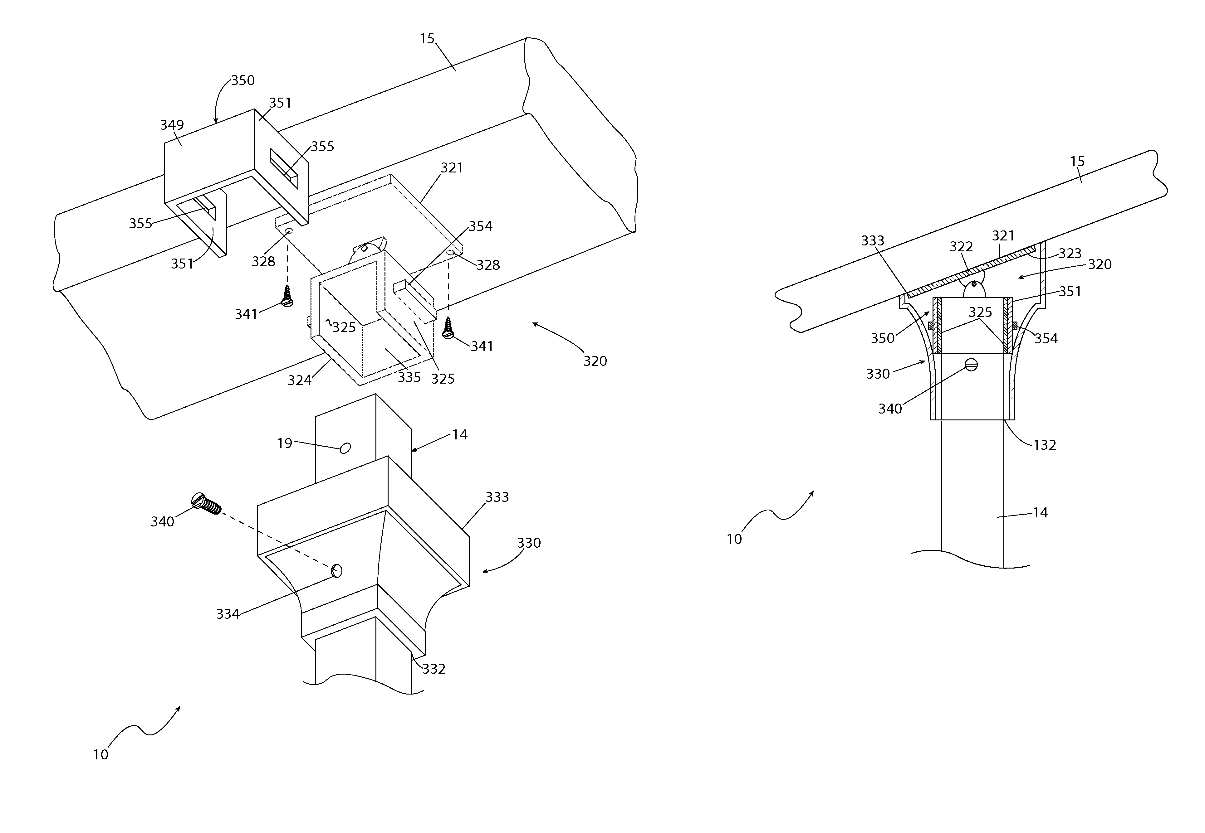
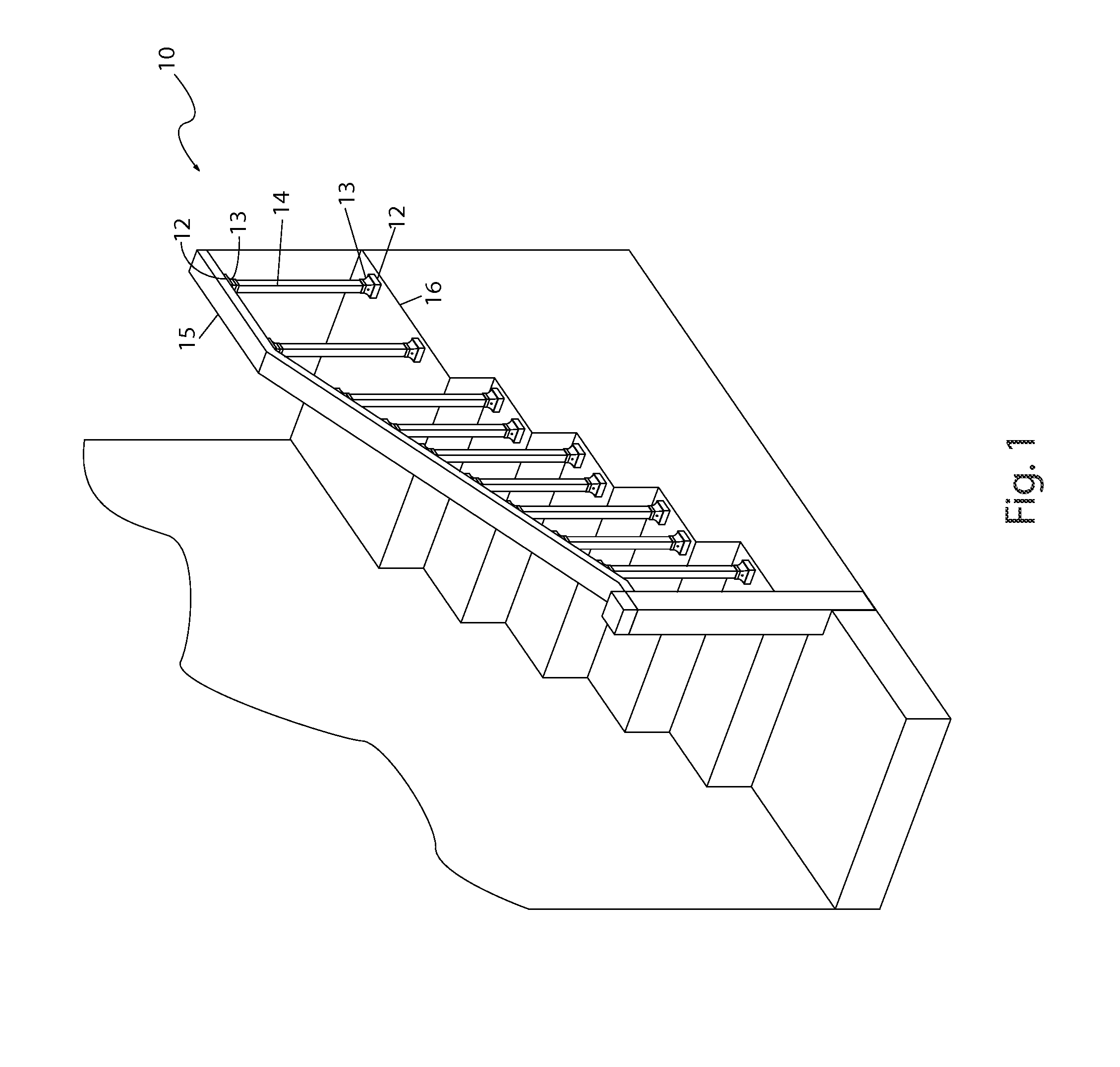
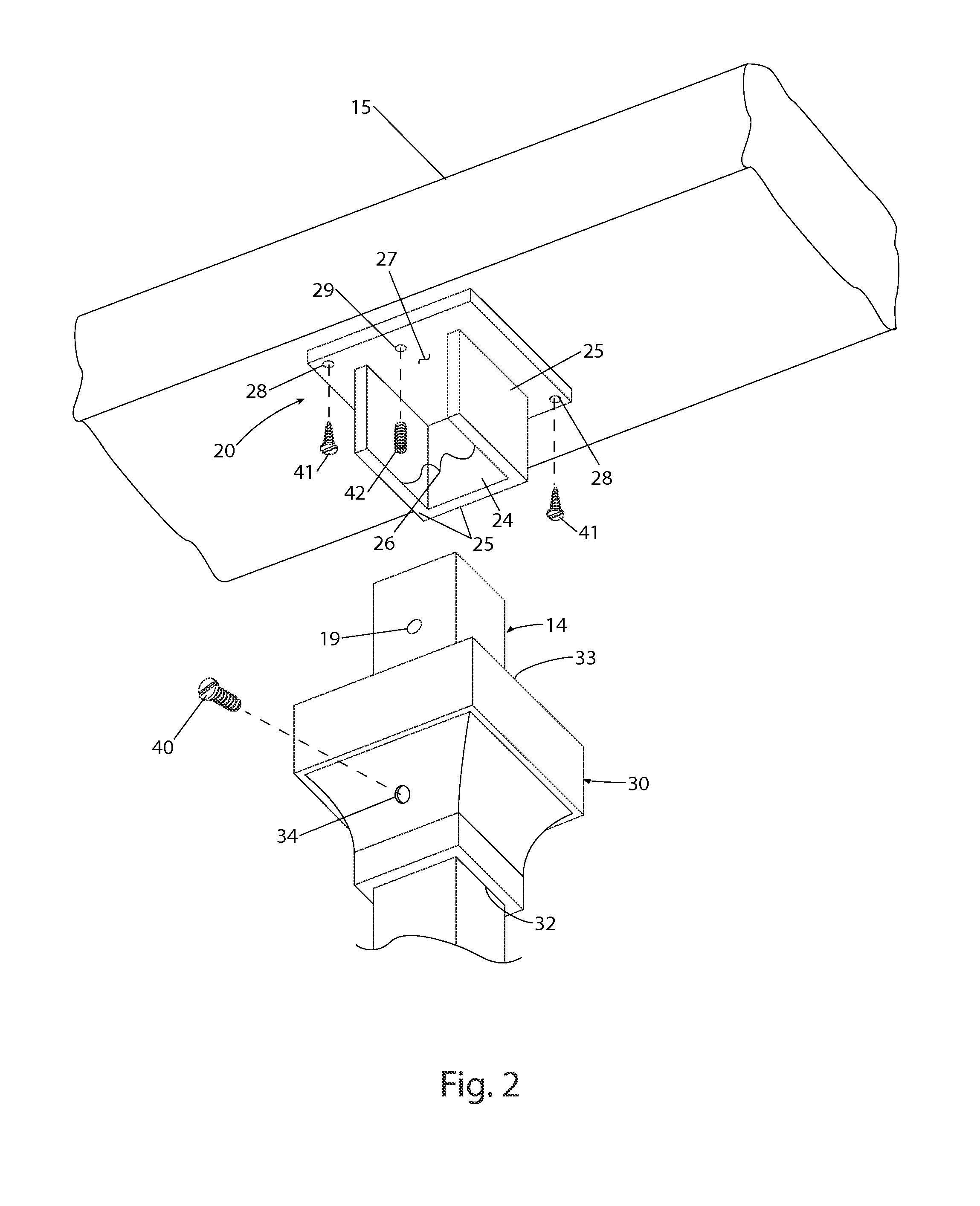
[0147]In accordance with the invention, the best mode is presented in terms of described embodiments, herein depicted within FIGS. 1 through 25. However, the disclosure is not limited to the described embodiments and a person skilled in the art will appreciate that many other embodiments are possible without deviating from the basic concept of the disclosure and that any such work around will also fall under its scope. It is envisioned that other styles and configurations can be easily incorporated into the teachings of the present disclosure, and only certain configurations have been shown and described for purposes of clarity and disclosure and not by way of limitation of scope.

[0148]It can be appreciated that, although such terms as first, second, etc. may be used herein to describe various elements, these elements should not be limited by these terms. These terms are only used to distinguish one (1) element from another element. Thus, a first element discussed below could be ter...


PUM


Abstract

A baluster bracket assembly including a pair of mounting brackets attached to facing surfaces of a handrail and a baserail for retaining a baluster in railing construction. Each mounting bracket includes a mounting plate fastened to the railing surface and a collar for receiving an end of the baluster. A shoe is provided with each mounting bracket for attachment to the end of the baluster and for covering the mounting bracket after installation.

Description

RELATED APPLICATIONS[0001]Continuation-in-part of application Ser. No. 13 / 400,262 filed on Feb. 20, 2012.FIELD OF THE INVENTION[0002]The present invention relates generally to railing construction, and in particular, to a baluster bracket assembly for the attachment of balusters between handrails and baserails in applications utilizing railing systems.BACKGROUND OF THE INVENTION[0003]A requirement for almost all walking-working surfaces is that every open-sided floor or platform four feet (4 ft.) or more above an adjacent floor or ground level shall be guarded by a railing on all open sides, except where there is an entrance to a ramp, stairway, or fixed ladder. The open space between a handrail and the floor surface is often filled by a plurality of spaced apart balusters. Most installers prefer to install balusters after the handrail is installed. The general consensus is that it is easier to adjust baluster position to fit the handrail than it is to measure, cut, fit, and attach ...

Claims


Application Information

Patent Timeline
IPC IPC(8): E04H17/14
CPCE04F2011/1827E04F11/1812E04F11/1814
Inventor SNEITH, JAYME, M.
Owner SNEITH JAYME M
Features
  • Generate Ideas
  • Intellectual Property
  • Life Sciences
  • Materials
  • Tech Scout
  • Unparalleled Data Quality
  • Higher Quality Content
  • 60% Fewer Hallucinations
Learn More