Flow rate measuring device

a technology of flow rate and measuring device, which is applied in the direction of instruments, diagnostic recording/measuring, applications, etc., can solve the problems of recurrent respiratory infections, death, health complications, and conventional methods,

Inactive Publication Date: 2015-01-20
EVANS CHERYL L
View PDF29 Cites 7 Cited by
  • Summary
  • Abstract
  • Description
  • Claims
  • Application Information

AI Technical Summary

Benefits of technology

[0017]Another aspect of the present invention is to provide a method for more accurately defining the type and severity of a patient's particular dysphagia.
[0019]An additional aspect of the present invention is to provide an apparatus enabling a medical professional to more accurately define the type and severity of a patent's dysphagia.
[0020]In that regard, a further aspect of the present invention is to provide an apparatus to enable a medical professional to prescribe a dysphagia diet that is customized to more accurately address the specific type and severity of a patient's dysphagia.
[0021]Another aspect of the present invention is to provide an apparatus that enables a treating speech therapist, caregiver, or patient to prepare or reproduce foods that are more accurately consistent with the prescribed dysphagia diet for a particular patient.
[0022]Furthermore, an aspect of the present invention is to provide an inexpensive and durable apparatus that accurately measures a quantifiable characteristic of liquid foods that enables the diagnosing professional to prescribe a customized dysphagia diet that addresses the needs for the specific type and severity of a patient's dysphagia, and then even further, enables a treating professional, caregiver, or the patient to accurately reproduce foods consistent with the parameters of the prescribed customized dysphagia diet for that particular patient.
[0023]Additional aspects of the present invention include (1) enabling patients to eliminate the cost of expensive prepackaged, commercially prepared food and liquid products, (2) enabling patients to make safe food and liquid choices, (3) enabling patients to stay within the confines of a prescribed quantified food characteristic range, (4) allowing patients to prepare foods and drinks at home that are more preferable to their specific taste and / or ethnic background than commercially prepared foods, and (5) eliminating health risks associated with consumption of inappropriate consistencies caused by using products from different manufacturers. It should be noted that the word “food” in this application refers to solid foods and liquid foods.

Problems solved by technology

Left untreated, dysphagia can cause health complications such as aspiration, malnutrition, dehydration, asphyxia, recurrent respiratory infections, and death.
The conventional method is problematic due to the inherent inconsistencies and ambiguousness of dysphagia diets.
In current practice, there is no set, uniform measurement to determine or replicate the thickness or consistency of the liquids and foods prescribed to a dysphagia patient.
Aspiration can have serious and deadly consequences to a patient's health, such as causing pneumonia, weight loss, fevers, recurrent respiratory illness, or even death.
Unfortunately, without a consistent, quantifiable measurement system, the perception of “honey,”“nectar” and “thin” liquids is so variable between people that they are rarely the same.
For a patient, such variations can be deadly.
The potential for problems, in terms of continua of care, increases with each transfer between treatment locations because of variability between caregivers in their perception of food consistencies.
A specific technical problem is the inability for a patient or their caregiver to quantifiably replicate the appropriate food consistency prescribed to the patient that would reduce adverse health risks due to their swallow dysfunction.
Neither of these current treatment methods is optimal.
In commercially prepared products, manufacturers use different techniques and machinery which are not consistent between manufactures.
Because of these inconsistencies, the patients may inadvertently consume an inappropriate consistency if they use products from different manufacturers, placing themselves at risk for aspiration or other health consequences.
Presently, there is no technique, procedure or method for clinical professionals, caregivers or patients to independently determine acceptable prescribed foods and liquids based on objective measures.

Method used


Image

  • Flow rate measuring device
  • Flow rate measuring device
  • Flow rate measuring device

Examples


first embodiment

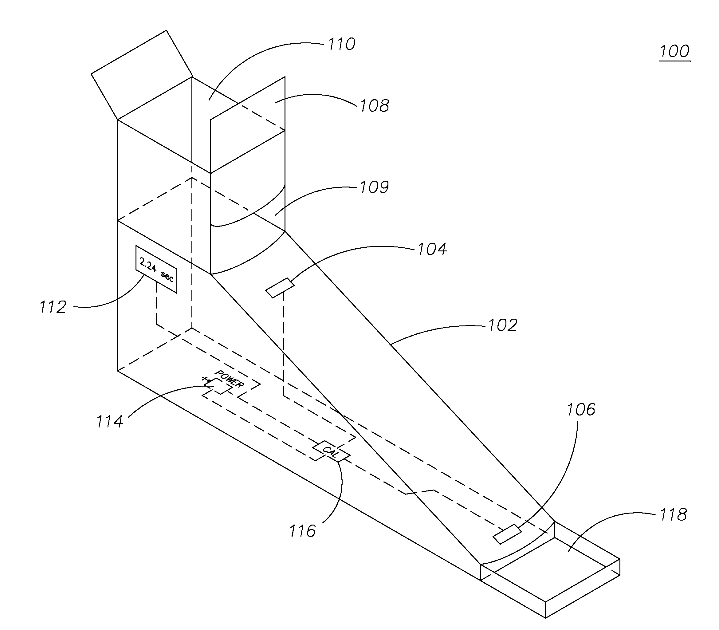
[0060]FIG. 3 illustrates a perspective view of a flow rate measuring device 100 configured in accordance with the present invention. The flow rate measuring device 100 has a ramp or chute 102 that includes a first liquid sensor 104 and a second liquid sensor 106. The liquid sensors 104,106 are located in the lower floor or curved section of the chute 102. Preferably, the liquid sensors 104,106 are covered with glass plates located within apertures in the chute 102, enabling the liquid sensors 104,106 to optically detect liquid as it flows over the liquid sensor 104 and then the liquid sensor 106. The liquid sensors 104,106 can be of a type disclosed in U.S. Pat. Nos. 3,558,898; 6,683,679; or 6,611,319, all of which are hereby incorporated by reference.

[0061]The upper portion of the chute 102 is connected to a reservoir or retention area 110. A vertical sliding gate 108 is formed into a wall of the retention area 110. The gate 108 can be slid up to create an opening 109 which allows ...

second embodiment

[0062]FIG. 4 illustrated another flow rate measuring device 200 configured in accordance with the present invention. The flow rate measuring device 200 is similar to a Bostwick consistometer with some additional improvements. A chute 202 is provided that can be constructed out of plastic or metal. The chute 202 includes a first liquid sensor 212 and a second liquid sensor 214, which may be similar to the liquid sensors 104,106 discussed above. The first and second liquid sensors 212,214 are preferably photo detectors, photo sensors, optical detectors, optical sensors, or any type of sensor capable of detecting presence or absence / decrease of light. Additionally, if the first and second liquid sensors are a type of light sensor, the detected light can be from, and is not limited to, any particular spectrum of light. For example, the sensors 212,214 could detect visible light, or ultraviolet light, or both. The liquid sensors 212, 214 are preferably flush with the surface of the chute...

third embodiment

[0065]Turning now to the present invention, FIGS. 5 and 6 illustrate a flow rate measuring device 300 configured in accordance with the present invention. FIG. 5 is a perspective view of the measuring device 300 from the same elevation, and FIG. 6 is a perspective view of the measuring device 300 looking down from a higher elevation. The flow rate measuring device 300 includes a housing 301 having a body 302 and a cover plate 304 on a front 305 of the body 302. An input port 306 for inputting and testing flowable food is located at a top 307 of the device 300, and a catch tray 308 is located at a bottom 309 of the device 300. Legs 310 and 312 are attached to the bottom 309 of the device 300 in order to stabilize the device 300. The legs 310 and 312 fit into slots 314 and 316 on the bottom 309 of the device 300.

[0066]A tip cup 318 is pivotally mounted to the upper portion 319 of the device 300. Flowable food to be tested by the device 300 initially can be placed within the tip cup 31...


PUM


Abstract

A flow rate measuring device having a housing for enclosing and preventing a removable ramp from being exposed to ambient light. The ramp includes an upper transparent section and a lower transparent section enabling a flowable substance to flow therebetween. A timing circuit connected to a first photo detector and a second photo detector below transparent sections of the ramp determines amount of time for a flowable substance to flow between the first photo detector and the second photo detector. Artificial light sources above the photo detectors are included within the housing.

Description

CROSS-REFERENCE TO RELATED APPLICATIONS[0001]This patent application is a continuation-in-part (CIP) of application Ser. No. 12 / 705,971, filed on Feb. 15, 2010, which claims priority and benefit of U.S. provisional patent application having application No. 61 / 152,726, filed on Feb. 15, 2009, and entitled “Method and Apparatus for Quantifying Dysphagia Foods for Patient Consumption.” Both of the patent applications referenced above in this paragraph are hereby incorporated by reference.FIELD OF THE INVENTION[0002]The present invention relates generally to flow rate measuring devices. More particularly, the present invention relates to a device for measuring the flow rates of flowable foods to facilitate diagnosing and preparing more accurate food diets for dysphagia patients.BACKGROUND OF THE INVENTION[0003]Dysphagia is a swallowing disorder, wherein a person is unable to swallow or has difficulty swallowing. Dysphagia is known to affect both adults and children, and can be associate...

Claims


Application Information

Patent Timeline
Patent Type & Authority Patents(United States)
IPC IPC(8): G01F1/708A61B5/00G09B19/00A61B5/11G01F1/00G01F1/712G01F1/7086
CPCG01F1/708G01F1/00G01F15/024G09B19/0092A61B5/11G01F1/7086A61B5/4205G01F1/712
Inventor EVANS, CHERYL, L.
Owner EVANS CHERYL L
Why Eureka
Try Eureka