IG window unit including double silver coating having increased SHGC to U-value ratio, and corresponding coated article for use in IG window unit or other window

a technology of ig window unit and double silver coating, which is applied in the direction of door/window protective device, transportation and packaging, and natural mineral layered products, etc., can solve the problems of poor thermal performance of building envelope and cost of heating the home, and achieve the effect of increasing the light to solar gain coefficient, low shgc values, and maximizing the transmission of light over solar energy

Active Publication Date: 2015-01-27
GUARDIAN GLASS LLC
View PDF29 Cites 28 Cited by
  • Summary
  • Abstract
  • Description
  • Claims
  • Application Information

AI Technical Summary

Benefits of technology

[0007]Conventional double silver low-E coatings (i.e., low-E coatings having two silver-based IR reflecting layers, in addition to other layers such as dielectric layers) have been developed to increase Light to Solar Gain (LSG) coefficient, meaning that the ratio of transmitted light over transmission of solar energy is maximized. Common LSG ratios of double silver low-E coatings range from 1.6 to 1.8, while the thermal insulation coefficient (U-value) of some is between 0.244 and 0.252. Most double silver coatings have the thicknesses of the silver layers nearly similar, with ratios of upper to lower Ag from 0.8 to 1.2. However, conventional double silver low-E coatings have low SHGC values and often high film-side reflectance and thus are undesirable in cold climates. For example, U.S. Pat. No. 8,142,622 teaches that low SHGC values are desirable and achieved with double-silver low-E coatings, thereby teaching away from the instant invention.
[0008]Conversely, conventional single Ag coatings (i.e., a low-F coating having just one silver-based IR reflecting layer, in addition to other layers such as dielectric layers) have been able to realize maximum solar transmission while maintaining acceptable U-value from 0.260 to 0.280 BTU/hr-ft2-° F. While increasing the Ag layer thickness can improve the U-value, it would undesirably decrease the Solar Heat Gain Coefficient (SHGC) and increase visible reflection (e.g., film side reflectance) which can both be undesirable. These coatings provide the current preferred solutions for cold climates and perform best per Quebec standards and requirements, though the U-value is greater than that of double silver coatings. However, in cold climates it is often desired to have a high SHGC, and it is also often desirable to have relatively low film-side reflectance for a coating so that the coating may be used on surface number three of an IG window unit, so that passive heat from the sun can makes its way into the building in order to help heat the building. Accordingly, conventional single silver low-E coatings cannot achieve a combination of a high SHGC to U-value ratio together with a low U-value and a low film-side reflectance. U.S. Pat. No. 8,409,717 discloses a single silver low-E coating, but it has undesirably high U-values. In particular, FIG. 3 of U.S. Pat. No. 8,409,717 shows that an IG window unit with this single silver coating suffers from high U-values of from 0.271 to 0.280.
[0009]Thus, it will be apparent that there is a need in the art for a window with a low-E coating that can realize one or more of, more preferably at least four or five of, and most preferably all six of: (i) an IG window unit having high visible transmission such as at least about 70%, (ii) an IG window unit having a high SHGC value such as at least 0.50, more preferably at least 0.52, even more preferably at least 0.54, even more preferably at least 0.56, with an example range being from about 0.50 to 0.60, in the out→in context of the IG window unit when the low-E coating is on surface three of the IG window unit as shown in FIG. 2, (iii) an IG window unit having a low outdoor/outside visible reflectance such as no greater than 15%, such as the low-E coating realizing low film-side reflectance when used on surface three of an IG window unit so that reflectance as viewed from the outside of the building is small, (iv) low emissivity and/or low sheet resistance, such as normal emissivity of no greater than 4% and more preferably no greater than 3%, (v) an IG window unit having an acceptable U-value such as a double glazing IG window unit with one low-E coating having a U-value of no greater than about 0.253 BTU/hr-ft2-° F., more preferably no greater than about 0.251 BTU/hr-ft2-° F., more preferably no greater than about 0.249, with an example range being from 0.244 to 0.253, more preferably from about 0.244 to 0.251 BTU/hr-ft2-° F., and (vi) a high SHGC to U-value ratio, calculated as SHGC/U-Value, of at least 2.0, more preferably of at least 2.10, even more preferably of at least 2.15, even more preferably of at least 2.20, more preferably at least 2.21, and most preferably of at least 2.24. Again, U-value herein is calculated according to NFRC 2010 at the center of the glazing (COG). And SHGC herein is calculated according to NFRC 2010, and is measured in this paragraph and otherwise herein in the out→in context of the IG window unit unless expressly stated otherwise. Example embodiments of this invention fulfill one or more of these needs, more preferably at least four or five of, and most preferably all six of these needs. In order to provide an advantageous combination of high visible transmission and high SHGC, in certain example embodiments of this invention, the ratio of the thickness of the bottom silver based IR reflecting layer to the thickness of the top silver based IR reflecting layer is from 0.30 to 0.50, more preferably from 0.38 to 0.47.
[0010]In certain example embodiments of this invention, there is provided an insulating glass (IG) window unit comprising: first and second glass substrates that are spaced apart from each other with a gap therebetween and substantially parallel to each other, wherein the first glass substrate is adapted to be at a building exterior and the second glass substrate is adapted to be closer to a building interior than is the first glass substrate; a low-E coating on a major surface of the second glass substrate facing said gap; the low-E coating comprising, moving away from the second glass substrate: (a) ...

Problems solved by technology

This means that the higher the U-value the worse the thermal performance of the building envelope.
However, peo...

Method used


Image

  • IG window unit including double silver coating having increased SHGC to U-value ratio, and corresponding coated article for use in IG window unit or other window
  • IG window unit including double silver coating having increased SHGC to U-value ratio, and corresponding coated article for use in IG window unit or other window
  • IG window unit including double silver coating having increased SHGC to U-value ratio, and corresponding coated article for use in IG window unit or other window

Examples


example 1

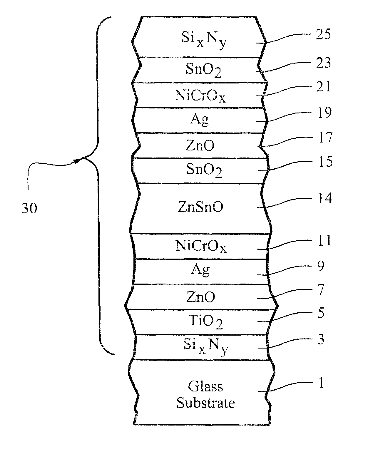
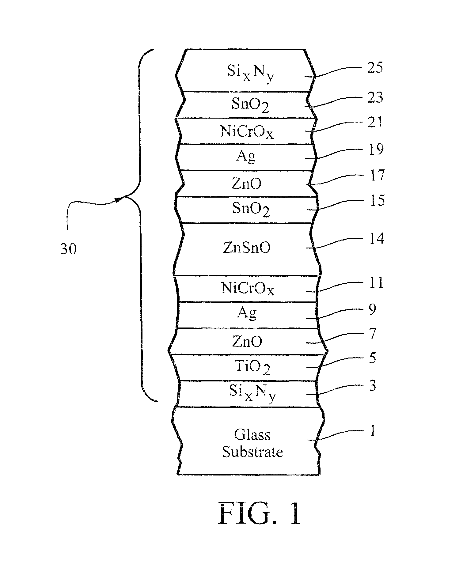
[0042]The following Example was made via sputtering on a 3.0 mm thick clear glass substrate 1 so as to have approximately the layer stack set forth below. This example is according to an example embodiment of this invention as shown in FIG. 1. The thicknesses are in units of angstroms (Å) and are approximations.

[0043]

Layer Glass SubstrateExample 1SixNy150TiO2108ZnAlO150Ag 56NiCrOx 30ZnSnO650SnO2100ZnAlO 82Ag116NiCrOx 30SnO2220Si3N4 220

[0044]The coated article of Example 1 had the following characteristics measured monolithically:

[0045]

Optical / Solar Characteristics (Ex. 1 monolithic; pre-IIT)CharacteristicValueTvis (or TY)(Ill. C. 2°):79.5% a*t (Ill. C. 2°): −1.01 b*t (Ill. C. 2°): +2.32RfY (Ill. C., 2 deg.): 6.1% a*f (Ill. C., 2°):+1.8 b*f (Ill. C., 2°):−9.78RgY (Ill. C., 2 deg.): 8.8% a*g (Ill. C., 2°):−0.69 b*g (Ill. C., 2°): −12.56

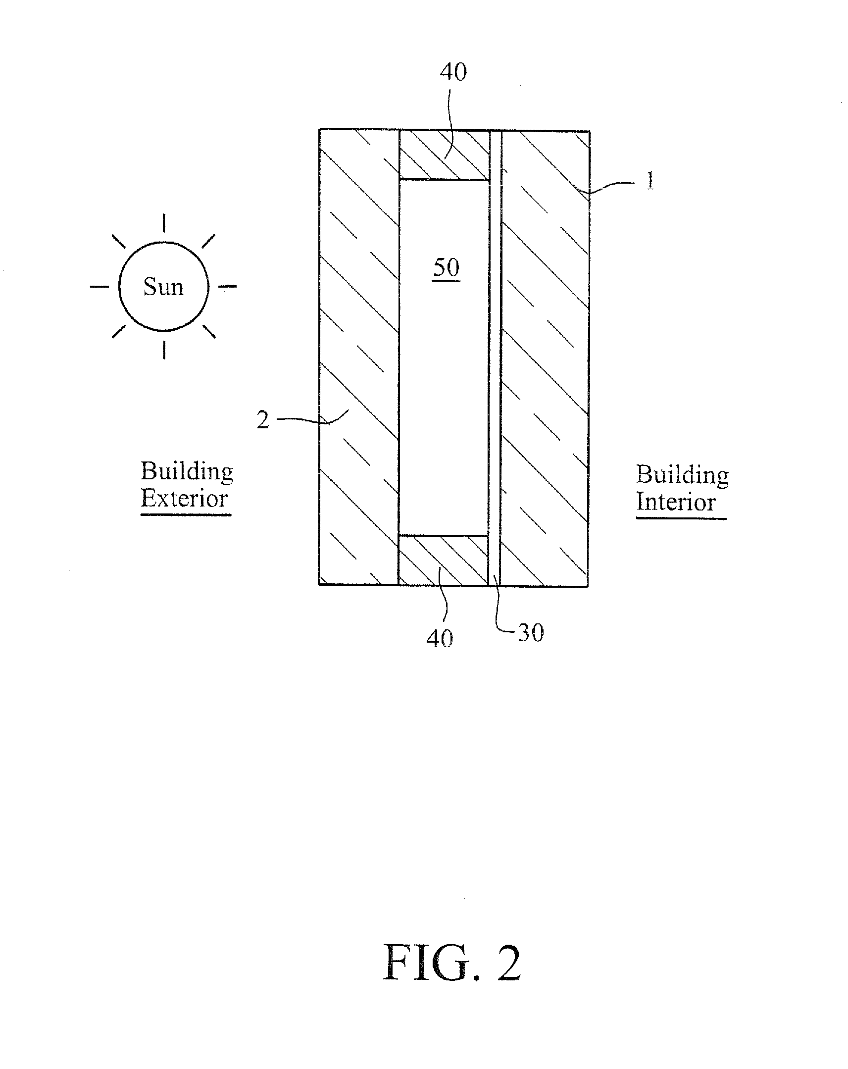
[0046]After being sputter deposited onto the glass substrate as shown in FIG. 1, the Example coated article was not thermally tempered and was provided...


PUM

PropertyMeasurementUnit
Fractionaaaaaaaaaa
Fractionaaaaaaaaaa
Energyaaaaaaaaaa

Abstract

An insulating glass (IG) window unit includes first and second substrates, and a low-emissivity (low-E) coating supported by one of the substrates. The low-E coating has two silver based infrared (IR) reflecting layers and allows the IG window unit to realize an increased SHGC to U-value ratio, and an increased thickness ratio of an upper silver based layer of the coating to a bottom silver based layer of the coating. The low-E coating is designed to have a low film-side reflectance, so that for example when the low-E coating is used on surface number three of an IG window unit the IG window unit can realize reduced visible reflectance as viewed from the outside of the building on which the IG window unit is mounted or is to be mounted.

Description

[0001]Certain embodiments of this invention relate to an insulating glass (IG) window unit including a low-emissivity (low-E) coating supported by a substrate such as a glass substrate, and / or to a corresponding coated article including a low-E coating supported by a glass substrate for use in the IG or other window unit. In certain example embodiments of this invention, the low-E coating is designed so as to allow the IG window unit to realize an increased SHGC to U-value ratio, and an increased thickness ratio of an upper silver based layer of the coating to a bottom silver based layer of the coating. In certain example embodiments, the low-E coating is designed to have a low film-side reflectance, so that for example when the low-E coating is used on surface number three of an IG window unit the IG window unit can realize reduced visible reflectance as viewed from the outside of the building on which the IG window unit is mounted or is to be mounted. In certain example embodiment...

Claims


Application Information

Patent Timeline
IPC IPC(8): B32B15/04B32B17/06
CPCC03C17/36C03C17/3626C03C17/3639C03C17/3644C03C17/366C03C17/3681Y10T428/2495E06B3/67C03C2217/211C03C2217/212C03C2217/216C03C2217/228C03C2217/281C03C2218/154E06B9/24E06B2009/2417
Inventor WUILLAUME, FRANCISBOYCE, BRENT
Owner GUARDIAN GLASS LLC
Why Eureka
Try Eureka