Variable power dimming control circuit

a control circuit and variable power technology, applied in the direction of electric variable regulation, process and machine control, instruments, etc., can solve the problems of consuming unnecessary power, affecting the operation quality of the driver circuit, and unable to operate normally in the triac, so as to reduce the total heat energy, facilitate the heat dissipation effect, and avoid unnecessary power consumption

Active Publication Date: 2015-01-27
EPISTAR CORP
View PDF9 Cites 36 Cited by
  • Summary
  • Abstract
  • Description
  • Claims
  • Application Information

AI Technical Summary

Benefits of technology

[0008]Therefore, it is a primary objective of the present invention to provide a variable power dimming control circuit that detects the magnitude of an input voltage power to timely output or stop outputting a basic voltage power for the normal operation of the holding TRIAC, so as to achieve the effects of improving the dimming stability of the whole circuit and reducing the unnecessary power consumption of the whole circuit.
[0009]To achieve the aforementioned objectives, the present invention provides a variable power dimming control circuit for driving and linearly adjusting the illumination brightness of a plurality of light emitting diodes (LEDs) which are electrically connected in series with each other or installed on a light board module, comprising: a dimming unit, a rectification unit, a dimming stabilization unit, a driving unit and a control unit. The rectification unit is electrically coupled to an external power supply through the dimming unit for receiving and rectifying an alternate current (AC) voltage of the external power supply and then outputting an input current. The dimming stabilization unit comprises a constant current device and a switch, and the constant current device is electrically coupled to the rectification unit and the switch for receiving the input current to generate a holding current. The driving unit is electrically coupled to the rectification unit, the constant current device and the light board module for receiving the input current and then supplying a driving current to the LEDs. The control unit comprises a detector, a controller, a current limiter and a feedback device, wherein the detector is electrically coupled to the rectification unit, the driving unit and the controller, and the controller is electrically coupled to the switch, the current limiter and the feedback device, and the current limiter is electrically coupled to the light board module and the feedback device. The detector is provided for receiving and detecting the input current to produce a detection value, and the feedback device is provided for receiving and sensing the driving current to produce a feedback value, and the controller is provided for comparing the detection value with the feedback value and then outputting a driving signal to drive the current limiter to adjust the current magnitude of the driving current, such that the input current Iin and the driving current IL satisfy the relation of Iin=IL, while the controller compares the feedback value with a reference value. If the feedback value is smaller than the reference value, a stable signal will be outputted to conduct the switch to allow the dimming stabilization unit to output the holding current, so that when the LEDs are dimmed to a minimum brightness or turned off, the input current Iin and the holding current Ihold satisfy the relation of Iin=Ihold for stabilizing the operating quality of the dimming unit and reducing unnecessary power consumption.
[0010]Wherein, the rectification unit is a full-wave bridge rectifier, and the dimming unit is a bidirectional TRIAC for receiving and adjusting an input phase conduction angle of the external power supply to change the input power and adjust the brightness of light emitted from the LEDs. The driving unit includes an isolator and a wave filter, and both ends of the isolator are coupled to the full-wave bridge rectifier and the wave filter respectively to obstruct the wave filter and the light board module to have a voltage change produced by a load change that affects the operating stability of the bidirectional TRIAC, and the wave filter is coupled to the LEDs for converting an input current transmitted from the isolator into the driving current and then transmitting the driving current to the LEDs to enhance the noise resistance of the circuit. The current limiter is an N-MOSFET, and the feedback device is a resistor component, and the current limiter has a drain coupled to the wave filter and the LEDs, a gate coupled to an output terminal of the controller, and a source coupled to the feedback device to constitute a negative feedback circuit architecture to provide a stable current control effect, and the current limiter is installed on a surface of the light board module to enhance the heat dissipation efficiency.
[0012]In summation of the description above, the present invention controls the output of the holding current by a simple switch component to avoid unnecessary power consumption caused by outputting the holding current continuously when the LEDs are adjusted to the maximum brightness, and further stops outputting the holding current to reduce the total heat energy produced by the operation of the circuit when the power consumption of the circuit is decreased, so as to facilitate the heat dissipation effect, assure the normal operation of electronic components and extend the service life. Even more, the dimming stabilization unit can transfer the input voltage power to the light board module through the power transfer component and the diode to facilitate converting the voltage power through the power transfer component when the switch is turned off and enhance the overall operating efficiency of the circuit.

Problems solved by technology

However, the TRIAC is a component that requires a standard operating voltage, so that if the conduction angle of the input power is too small and the overall operating voltage of the circuit has a voltage power smaller than a standard operating voltage required by the TRIAC, the TRIAC will be unable to operate normally, and the operating quality of the driver circuit will be affected adversely.
In other words, regardless of the magnitude of the input power of the circuit, the holding current keeps operating, and thus causing the problems of consuming unnecessary power and lowering the power conversion efficiency of the whole circuit.

Method used


Image

  • Variable power dimming control circuit
  • Variable power dimming control circuit
  • Variable power dimming control circuit

Examples


Embodiment Construction

[0021]The technical content of the present invention will become apparent with the detailed description of preferred embodiments and the illustration of related drawings as follows.

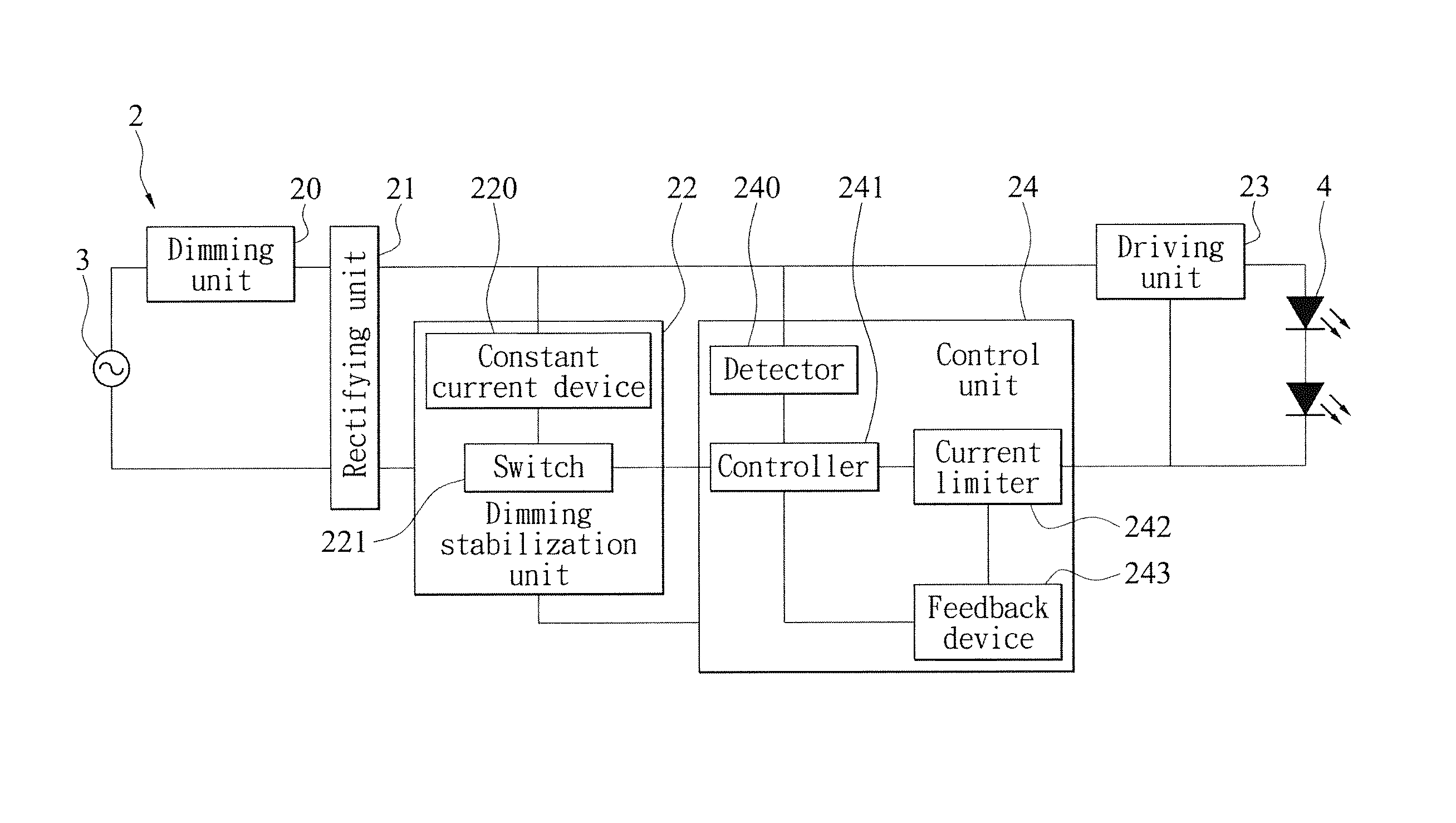
[0022]With reference to FIGS. 3 to 5 for block diagrams of two implementation modes and a circuit diagram of a preferred embodiment of the present invention respectively. As shown in the figures, a variable power dimming control circuit 2 is installed at a light board module (not shown in the figures) of a lamp for converting a voltage power of an external power supply 3 to drive and linearly adjust the illumination brightness of a plurality of LEDs 4, and the LEDs 4 are electrically connected in series or in parallel and installed on the light board module. The variable power dimming control circuit 2 comprises a dimming unit 20, a rectification unit 21, a dimming stabilization unit 22, a driving unit 23 and a control unit 24, and the dimming stabilization unit 22 comprises a constant current device 220 ...


PUM


Abstract

Disclosed is a variable power dimming control circuit for driving and linearly adjusting the illumination brightness of a plurality of light emitting diodes (LEDs), and the circuit includes a dimming stabilization unit and a control unit. The control unit is provided for detecting an input current of a circuit, and the dimming stabilization unit is driven for outputting a holding current when the input power is smaller than a standard, and stopping the output the holding current when the input power is greater than the standard. When the LEDs are dimmed to low luminance, a chip controls the operation of the dimming stabilization unit to assure the stability of the dimming operation of a TRIAC. When the LEDs are adjusted to high or full brightness, the chip stops the output of the holding current to reduce unnecessary power consumption and enhance the overall circuit performance effectively.

Description

CROSS-REFERENCE TO RELATED APPLICATIONS[0001]This non-provisional application claims priority under 35 U.S.C. §119(a) on Patent Application No(s). 102115052 filed in Taiwan, R.O.C. on Apr. 26, 2013, the entire contents of which are hereby incorporated by reference.BACKGROUND OF THE INVENTION[0002]1. Field of the Invention[0003]The present invention relates to the field of light emitting diode (LED) power devices, and more particularly to a variable power dimming control circuit that supports the linear light dimming of a bi-directional TRI-electrode AC (TRIAC) switch and provides a holding current to stabilize the operating quality of the TRIAC switch when the LED is dimmed to a low brightness, and stops supplying the output of the holding current when the brightness of the LED is increased, so as to achieve the effects of reducing unnecessary power consumption of the circuit and minimizing the heat produced during the operation of the LED.[0004]2. Description of the Related Art[000...

Claims


Application Information

Patent Timeline
Patent Type & Authority Patents(United States)
IPC IPC(8): H05B37/02H05B44/00
CPCH05B33/0845Y02B20/30H05B45/3725H05B45/397H05B45/10
Inventor WU, CHIH-HSIENCHANG, WEILU, HUAN-YINGCHUANG, KAI-CHENGCHIU, SHAO-WEI
Owner EPISTAR CORP
Why Eureka
Try Eureka