Optically pumped magnetometer and magnetic sensing method

a magnetometer and optical pumping technology, applied in the field of optical pumping magnetometers and magnetic sensing methods, can solve the problems of no known optical pumping magnetometer and conventional optical pumping magnetometers

Active Publication Date: 2015-01-27
CANON KK
View PDF11 Cites 43 Cited by
  • Summary
  • Abstract
  • Description
  • Claims
  • Application Information

AI Technical Summary

Problems solved by technology

However, conventional optically pumped magnetometers have the following problems.
There is no known optically pumped magnetometer that acquires information as to strengths of magnetic fields in two different directions.

Method used


Image

  • Optically pumped magnetometer and magnetic sensing method
  • Optically pumped magnetometer and magnetic sensing method
  • Optically pumped magnetometer and magnetic sensing method

Examples


embodiment 1

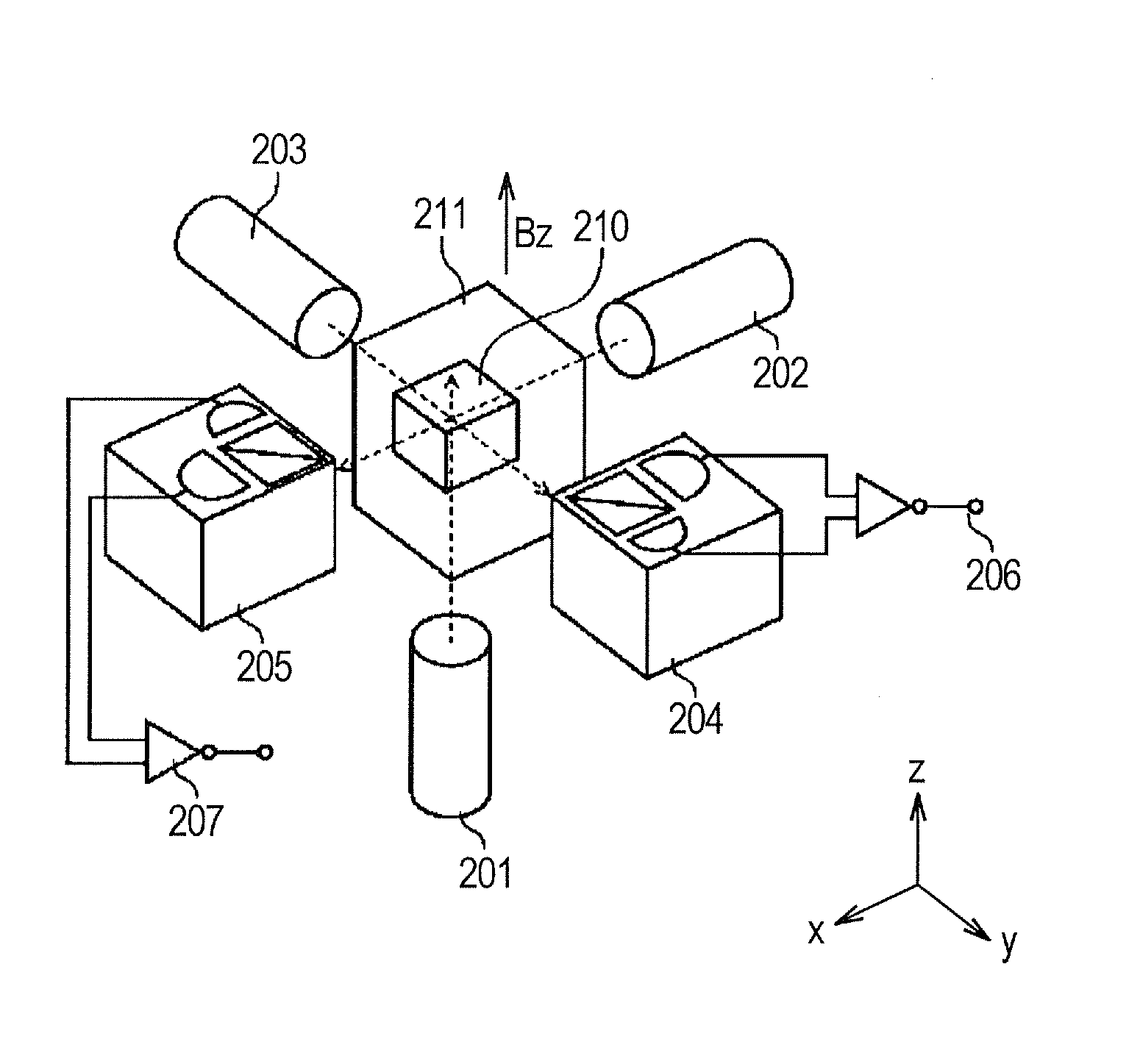
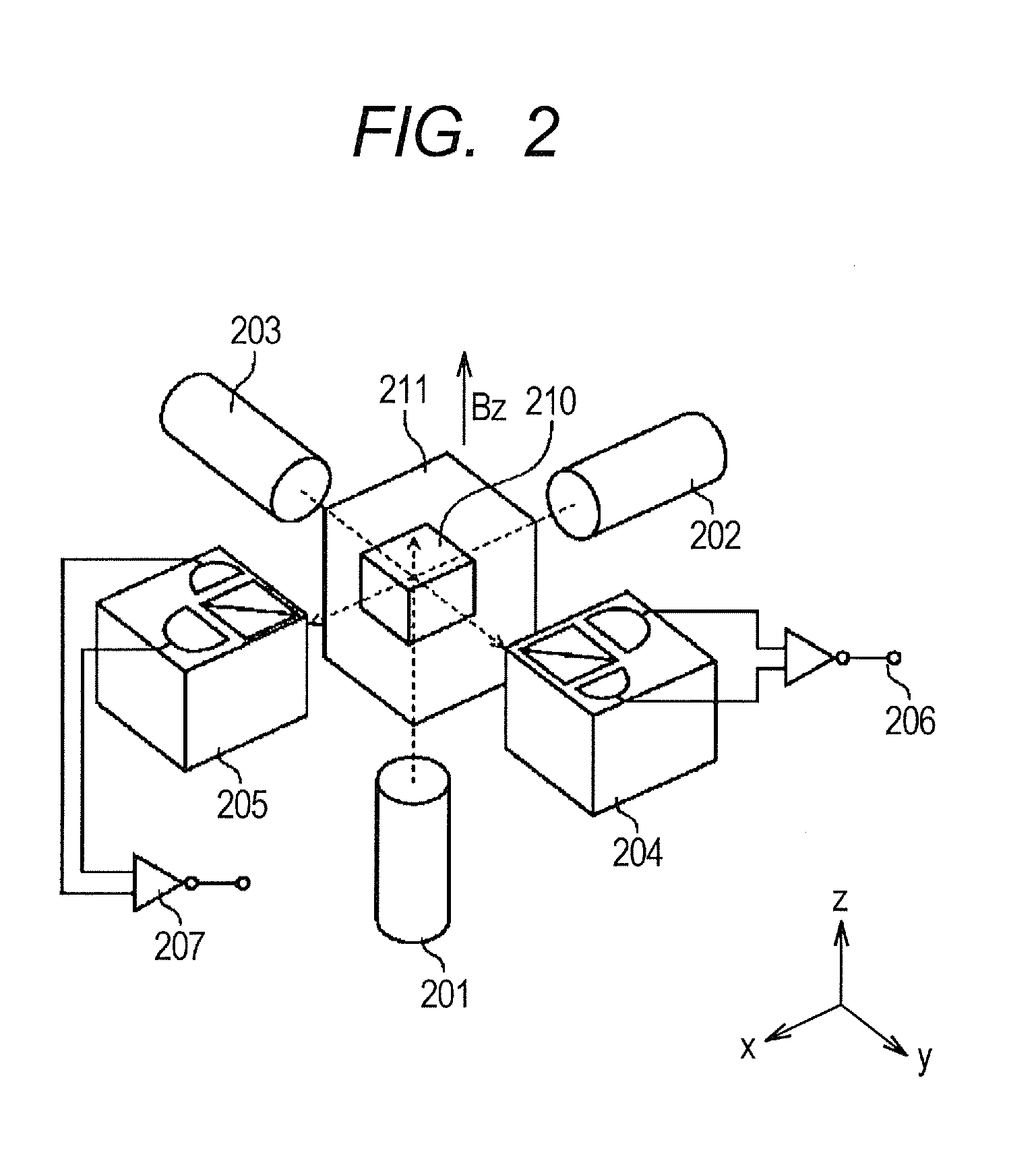
[0024]An optically pumped magnetometer according to Embodiment 1 includes the following components. The optically pumped magnetometer includes a cell containing a group of alkali metal atoms, a pump light optical system that launches pump light having a circularly polarized component into the cell, a first probe light optical system that launches first probe light having a linearly polarized component into the cell so as to cross the pump light in the cell, and a second probe light optical system that emits second probe light having a linearly polarized component so as to cross the pump light and the first probe light in the cell. The optically pumped magnetometer further includes a first detector that detects the rotation angle of the plane of polarization of the first probe light having passed through the cell, and a second detector that detects the rotation angle of the plane of polarization of the second probe light having passed through the cell. The optically pumped magnetomet...

embodiment 2

[0048]An optically pumped magnetometer according to Embodiment 2 of the present invention will be described. Description of items common to Embodiments 1 and 2 will be omitted, and differences between Embodiments 1 and 2 will be described. The optically pumped magnetometer according to this embodiment includes the following components. That is, an optically pumped magnetometer calculating unit according to this embodiment includes a first calculating unit that calculates the rotation angle of the polarization plane detected by the first detector, the frequency spectrum of the rotation angle of the polarization plane detected by the first detector, and the frequency spectrum of the rotation angle of the polarization plane detected by the second detector. The optically pumped magnetometer calculating unit further includes a second calculating unit that calculates information as to the strengths of the magnetic fields in the two directions from the frequency spectrum of the rotation an...

specific examples of embodiment

[0050]In the following, specific examples of the optically pumped magnetometer capable of acquiring information as to the strengths of magnetic fields in two different directions and the magnetic sensing method according to one of the embodiments described above (embodiment 1) will be described. The approximation described below is introduced to the first and second equations in the Bloch equations (1). A small change in Sz is ignored, and the z component Sz is regarded as a constant value. The transverse relaxation rate T2 is regarded as a constant and separately determined in advance from the last measurement, for example. Using the discrete data Sxi and Syi obtained by measurement, the differential term is replaced with a difference expressed using Sxi, Sxi+1, Syi and Syi+1.

[0051]ⅆⅆt⁢Sr⁡(ti+Δ⁢⁢t2)≈Sri+1-SriΔ⁢⁢t⁢⁢(r=x,y)Formula⁢⁢(5)

[0052]As for Sx and Sy, the value S at a time ti+[(ti+1−ti) / 2] is interpolated according to the following formula (6) using the values Sxi, Sxi+1, Syi ...


PUM


Abstract

An optically pumped magnetometer and a magnetic sensing method acquire information as to strengths of magnetic fields in two different directions. A pump light having a circularly polarized component, first probe light having a liner polarized component and second probe light having a linearly polarized component are emitted to a cell containing a group of alkali metal atoms so as to form a crossing region A magnetic field applying unit applies a static magnetic field in a direction of the pump light incident on the crossing region during the emission of the pump light, the first probe light and the second probe light. And, information as to strengths of magnetic fields in two different directions perpendicular to the direction of the static magnetic field in the cell from the rotation angles of a polarization planes of the first and second probe lights during passage through the cell is calculated.

Description

BACKGROUND OF THE INVENTION[0001]1. Field of the Invention[0002]The present invention relates to an optically pumped magnetometer and a magnetic sensing method.[0003]2. Description of the Related Art[0004]Optically pumped magnetometers using electron spins of alkali metal gas are known. For example, in Japanese Patent Application Laid-Open No. 2009-14708, an atomic magnetometer whose probe light beam is given from one direction is proposed. In Japanese Patent Application Laid-Open No. 2011-106968, a magnetic measurement apparatus whose probe light beam is given from two directions to acquire magnetic information. However, conventional optically pumped magnetometers have the following problems.[0005]The optically pumped magnetometers whose probe light beam is given from one direction, such as the one disclosed in Japanese Patent Application Laid-Open No. 2009-14708, can acquire only information as to a magnetic field in one direction. Japanese Patent Application Laid-Open No. 2011-10...

Claims


Application Information

Patent Timeline
Patent Type & Authority Patents(United States)
IPC IPC(8): G01R33/02
CPCG01R33/032
Inventor MIZUTANI, NATSUHIKOKOBAYASHI, TETSUO
Owner CANON KK
Why Eureka
Try Eureka