Polarization-maintaining optical fiber, method of manufacturing polarization-maintaining optical-fiber connecting portion, and polarization-maintaining optical-fiber connecting portion

a technology of polarization-maintaining optical fiber and polarization-maintaining optical fiber, which is applied in the direction of optical fibers with polarisation, manufacturing tools, instruments, etc., can solve the problems of reducing modal birefringence, reducing polarization maintaining property, and greatly increasing macro-bending loss

Inactive Publication Date: 2010-10-05
FURUKAWA ELECTRIC CO LTD
View PDF21 Cites 223 Cited by
  • Summary
  • Abstract
  • Description
  • Claims
  • Application Information

AI Technical Summary

Benefits of technology

[0011]Moreover, according to still another aspect of the present invention, there is provided a method of manufacturing a polarization-maintaining optical-fiber connecting portion including fusion splicing a polarization-maintaining optical fiber that includes a core region and a cladding region formed around the core region, the cladding region having a refractive index lower than a refractive index of the core region, wherein a refractive index profile of the core region is either one of a step shaped or a concave shaped, and the cladding region includes two holes formed in such a manner that a shortest distance from the core region is virtually zero at locations in opposite to each other across the core region, and a stress-applying-type polarization-maintaining optical fiber by aligning polarization axes of the polarization-maintaining optical fiber and the stress-applying-type polarization-maintaining optical fiber in such a manner that the holes at a facet of the polarization-maintaining optical fiber are not collapsed; and forming an elliptic core region at the facet by heating the facet of a fusion spliced polarization-maintaining optical fiber so that the holes are collapsed.

Problems solved by technology

However, the polarization-maintaining optical fiber disclosed in Japanese Patent Application Laid-Open No. 2004-264405 has a problem that the gap between the core region and the holes decreases the modal birefringence, so that the polarization maintaining property is degraded.
In addition, there is a problem that the macro-bending loss is greatly increased, if the core diameter is decreased.

Method used


Image

  • Polarization-maintaining optical fiber, method of manufacturing polarization-maintaining optical-fiber connecting portion, and polarization-maintaining optical-fiber connecting portion
  • Polarization-maintaining optical fiber, method of manufacturing polarization-maintaining optical-fiber connecting portion, and polarization-maintaining optical-fiber connecting portion
  • Polarization-maintaining optical fiber, method of manufacturing polarization-maintaining optical-fiber connecting portion, and polarization-maintaining optical-fiber connecting portion

Examples


first embodiment

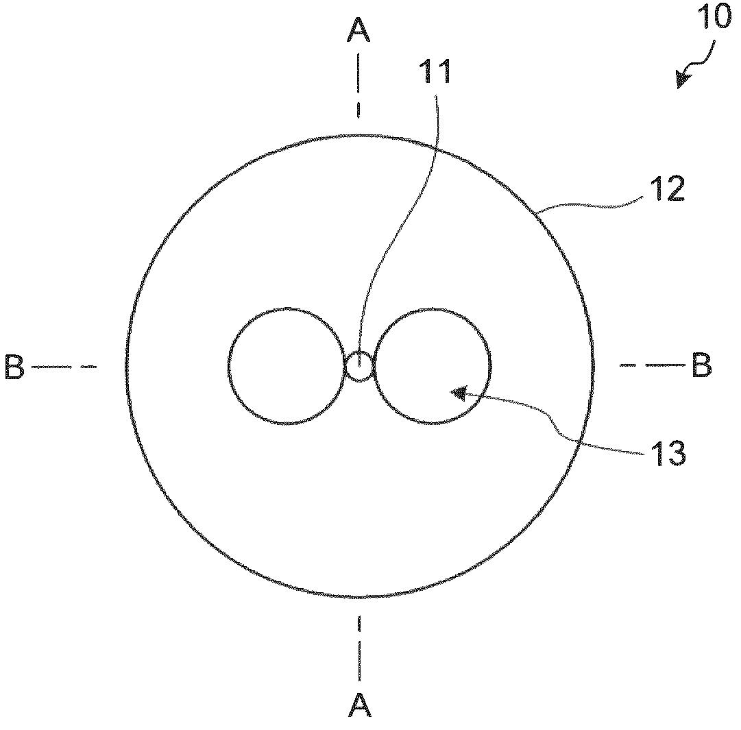
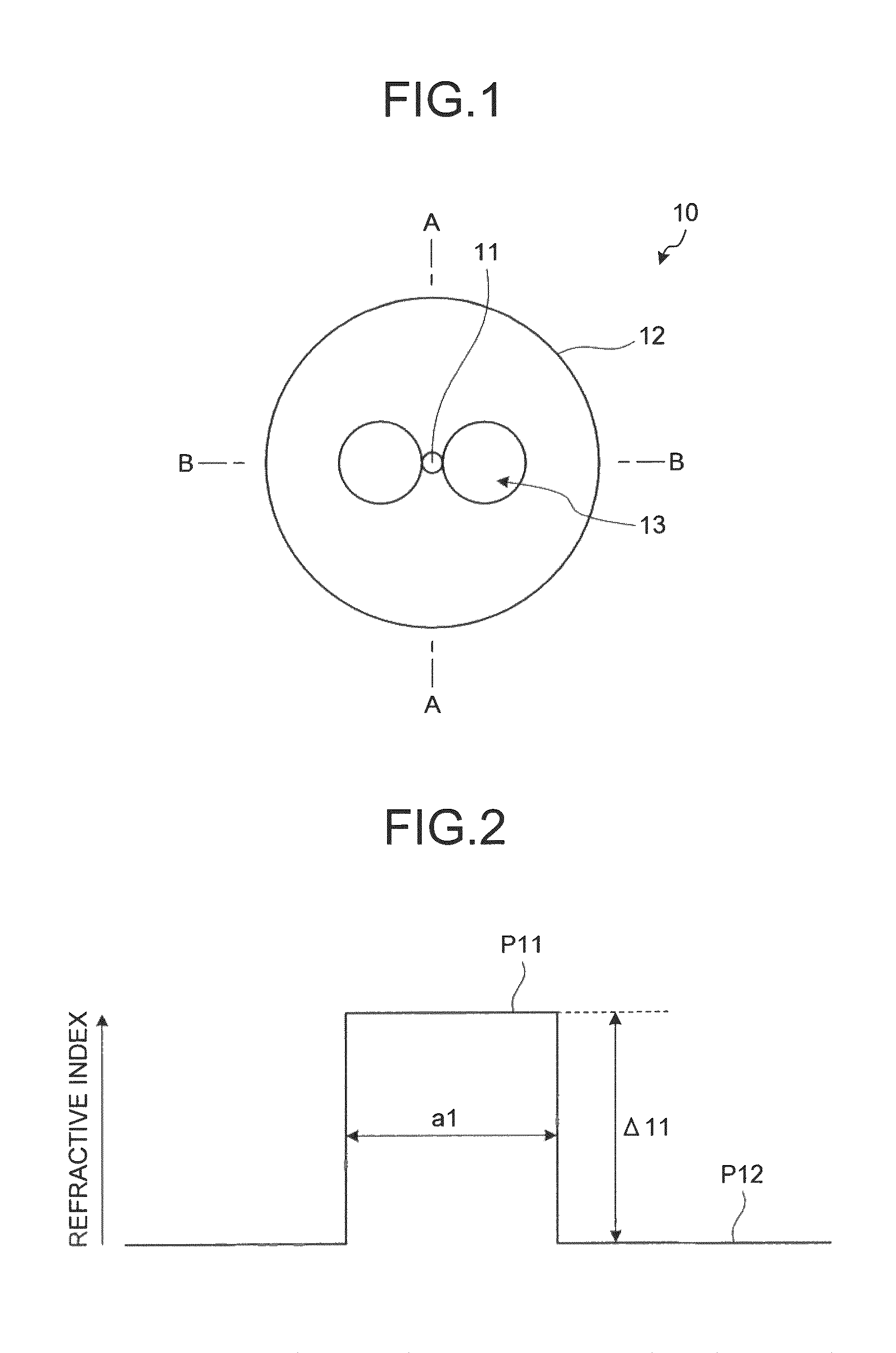
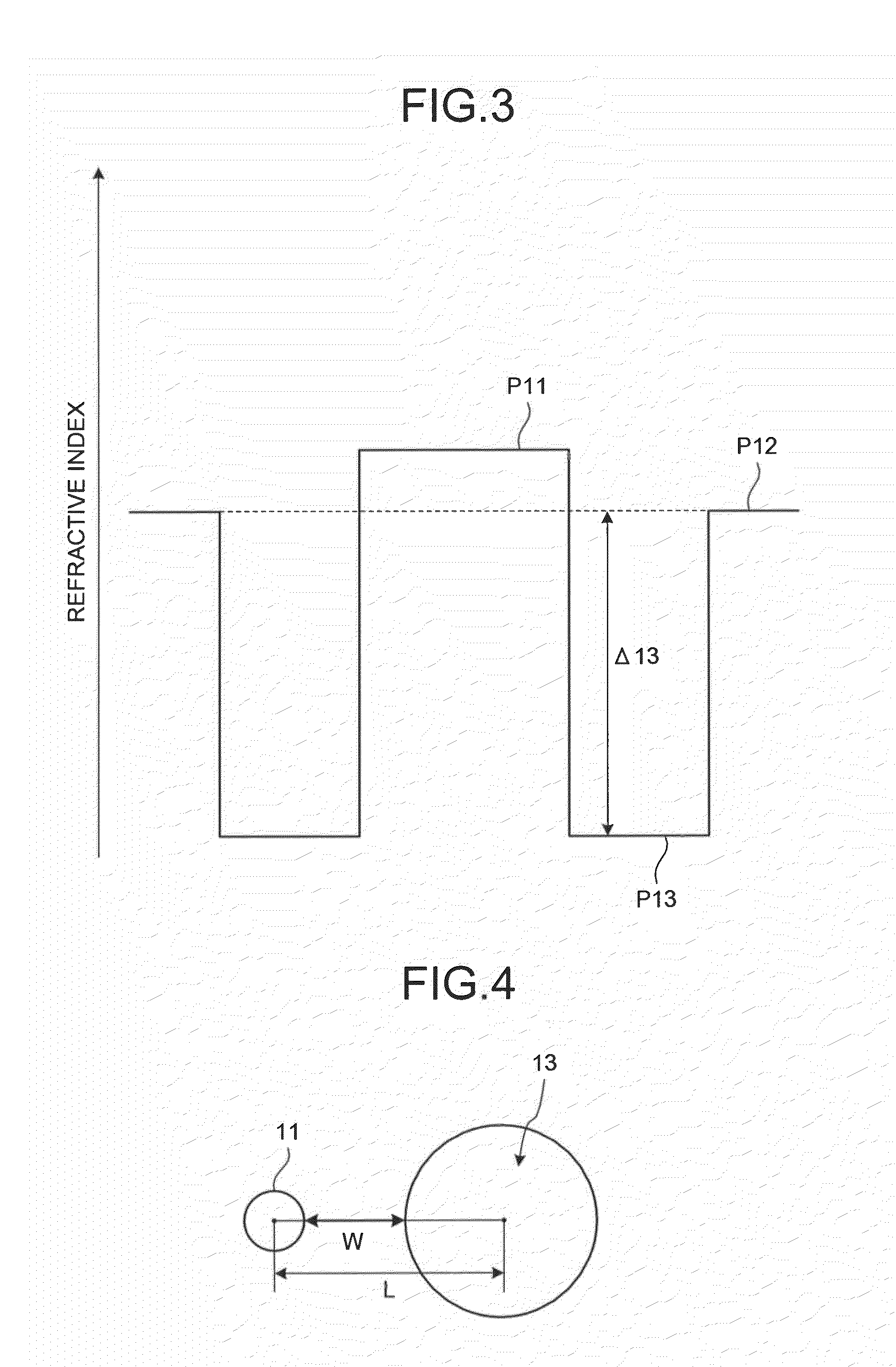
[0034]FIG. 1 is a schematic cross section of a polarization-maintaining optical fiber 10 according to the present invention. As shown in FIG. 1, the polarization-maintaining optical fiber 10 includes a core region 11 and a cladding region 12 that is formed on the outer circumference of the core region 11. The refractive index of the cladding region 12 is lower than that of the core region 11. The core region 11 is made of germanium-doped silica glass, and the cladding region 12 is made of pure silica glass into which no dopant for adjusting the refractive index is doped. The cladding region 12 has two holes 13 opposite to each other across the core region 11. Either of the holes 13 is formed in such a manner that the minimum distance from the core region 11 is virtually zero. The minimum distance will be explained in detail later.

[0035]FIG. 2 is a schematic diagram illustrating a refractive index profile of the polarization-maintaining optical fiber 10 shown in FIG. 1 at a cross sec...

second embodiment

[0076]As polarization-maintaining optical fibers according to a fifteenth to a twentieth embodiment examples, a polarization-maintaining optical fiber having the same structure as the polarization-maintaining optical fiber with changes of the relative refractive index differences of the center core region and the outer core region, the diameter of the center core region, the core diameter of the core region and the α value, and the hole diameter of the holes has been fabricated.

[0077]FIG. 13 is a table showing the characteristics of the polarization-maintaining optical fiber according to the fifteenth to the twentieth embodiment examples. In FIG. 13, “Δ21” is the relative refractive index difference of the center core region, “Δ22” is the relative refractive index difference of the outer core region, “α2” is the α value, “a21” is the diameter of the center core region, and “a22” is the core diameter. In this case, the α value is an α value obtained when the profile from a position ...

fourth embodiment

[0085]FIG. 17 is a schematic diagram for explaining the method of manufacturing a polarization-maintaining optical-fiber connecting portion according to the First, as shown in FIG. 17, the polarization-maintaining optical fiber 10 and the stress-applying-type polarization-maintaining optical fiber 40 are fusion spliced using a conventional fusion splicer in a state in which the polarization axes are matched. In this case, because the holes 13 formed in the polarization-maintaining optical-fiber 10 become marks for matching the polarization axes, it is possible to match the polarization axes by performing the core matching using an image processing function of the conventional fusion splicer in such a manner that the arrangement direction of the holes 13 of the polarization-maintaining optical fiber 10 becomes identical to the arrangement direction of the stress applying members 43 of the stress-applying-type polarization-maintaining optical fiber 40. The fusion splicing is performe...


PUM

PropertyMeasurementUnit
refractive index profileaaaaaaaaaa
wavelengthaaaaaaaaaa

Abstract

A polarization-maintaining optical fiber includes a core region and a cladding region formed around the core region. The cladding region has a refractive index lower than a refractive index of the core region. A refractive index profile of the core region is either one of a step shaped or a concave shaped. The cladding region includes two holes formed in such a manner that a shortest distance from the core region is virtually zero at locations in opposite to each other across the core region.

Description

CROSS-REFERENCE TO RELATED APPLICATIONS[0001]This application is a continuation of PCT / JP2007 / 063915 filed on Jul. 12, 2007, the entire content of which are incorporated herein by reference.BACKGROUND OF THE INVENTION[0002]1. Field of the Invention[0003]The present invention relates to a side-tunnel-type polarization-maintaining optical fiber, a method of manufacturing a polarization-maintaining optical-fiber connecting portion, and a polarization-maintaining optical-fiber connecting portion.[0004]2. Description of the Related Art[0005]The polarization-maintaining optical fiber is an optical fiber that propagates a light while maintaining a polarization state of the light. A stress-applying-type polarization-maintaining optical fiber in which orthogonal axes having different effective refractive index from each other are formed by arranging stress applying members in opposite to each other across the core region and an elliptic-core-type polarization-maintaining optical fiber includ...

Claims


Application Information

Patent Timeline
Patent Type & Authority Patents(United States)
IPC IPC(8): G02B6/024G02B6/255
CPCC03B37/01466G02B6/024C03B2203/12C03B2203/29C03B2203/30C03B2203/22
Inventor MIYABE, RYOMIMURA, YU
Owner FURUKAWA ELECTRIC CO LTD
Why Eureka
Try Eureka