
Efficient two-panel projection system employing complementary illumination

a projection system and complementary technology, applied in the field of efficient two-panel projection system employing complementary illumination, can solve the problems of limiting the overall gain in lumens possible, inefficient single-panel system, and limited availability of higher-power lamps

Inactive Publication Date: 2001-08-28
PHILIPS ELECTRONICS NORTH AMERICA
View PDF14 Cites 227 Cited by
  • Summary
  • Abstract
  • Description
  • Claims
  • Application Information

AI Technical Summary

Benefits of technology

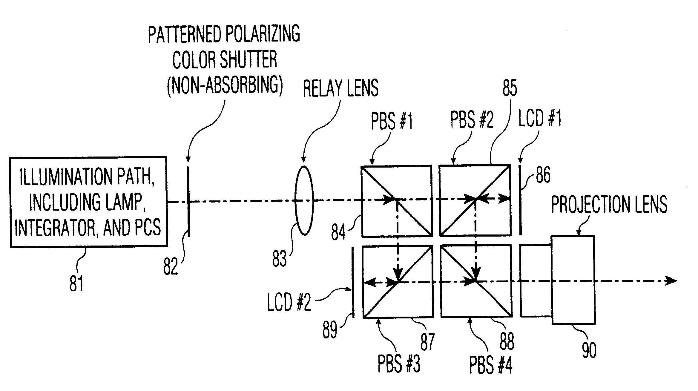
The present invention provides a system which seeks to efficiently use substantially all of the light output of a projector illumination source by splitting the light into two components based on color, and separately modulating each split color component. In order to achieve full color range, the wavelength characteristics of the color splitter are varied in time sequential manner, to provide increased coverage of the full color gamut.
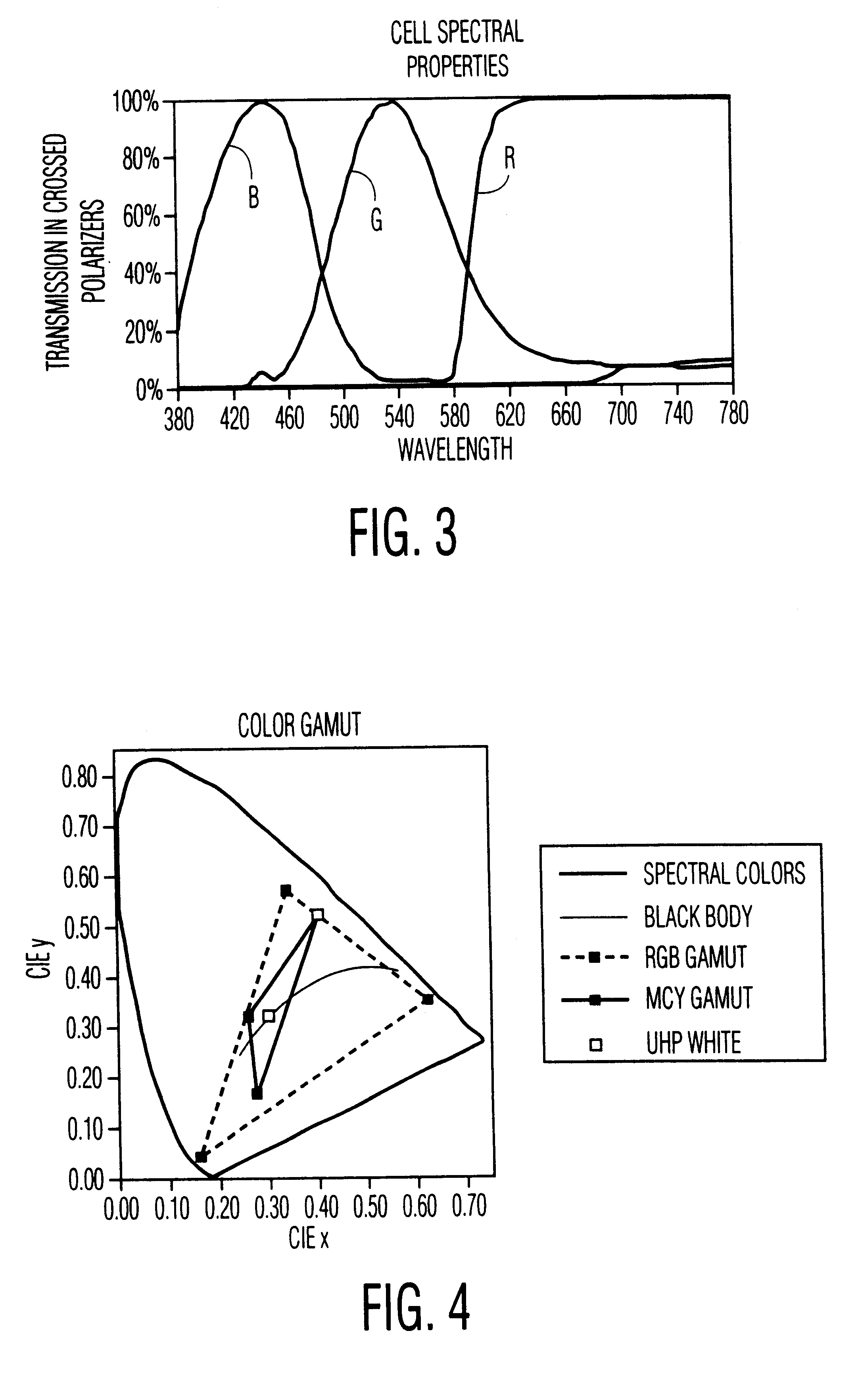
It is noted that according to a preferred embodiment of the present invention, there are substantial advantages over a red, green, blue, white system, and further, little or nothing would be gained by employing a greater number of complementary color pairs than three. Specifically, there would be no benefit from adding a white / black complementary pair. Since the complementary color of white is black, during the black period one liquid crystal display device is unused. Using three complementary pairs, i.e. red / cyan, green / magenta, and blue / yellow provides all the lumen throughput benefits of a red, green, blue, white system while avoiding most of the color saturation problems associated with a prior art red , green, blue, white system.

Problems solved by technology

These single panel systems are known to be inefficient.
In addition, the availability of higher power lamps may be limited, and thus higher efficiency may result in more available light sources.
This limits the overall gain in lumens possible with this technique.

Method used


Image

  • Efficient two-panel projection system employing complementary illumination
  • Efficient two-panel projection system employing complementary illumination
  • Efficient two-panel projection system employing complementary illumination

Examples


example 2

One variation in the color sequencing occurs if one LCD, for example the first LCD 86, is assigned to produce the green, cyan (green+blue) and yellow (green+red) fields, while the other LCD 89 is assigned the red, blue and magenta (red+blue) fields. With this arrangement, the green light never needs to go to the second LCD 89. Therefore, the polarization of the green light in the incoming white light is never modified by the E-SPF, and further, the E-SPF need only be a 2 layer device capable of modifying the polarization of red and blue light rather than a three layer device capable of modifying the polarization of all three colors. Of course, it is obvious that modulation of the polarization of any pair of colors is sufficient to produce a 6 primary color projector: red / blue as in the example, or red / green or blue / green.

It is further noted that, instead of providing a two-layer E-SPF with red and blue modulation, the E-SPF 82 may provide blue and green modulation, thereby assigning...

example 3

In the embodiments described above, the E-SFP 82 is presumed to act in concert with global addressing, i.e., the entire area of each LCD and the color shutter change state simultaneously. See, Shields, U.S. Pat. No. 4,870,396, expressly incorporated herein by reference.

This is not the most common manner of addressing LCDs, however. In the typical LCD (reflective or transmissive) the data is loaded into one row at a time and the state of the LCD changes immediately after the data is loaded. Take, for example, the case of a single panel color sequential system where the data is loaded in the order red, green, blue. While the red data is loading into a row, it is overwriting the blue data in that line from the previous field. As soon as a row is finished loading, the addressing circuitry drops down to the next row and loads the red data for that row, overwriting the previous blue data. Therefore, there is a line traveling down the LCD with blue data below the line and red data above th...

example 4

The present projection system would also work for transmissive LCDs, as shown in FIG. 8. In this case, two plane fold mirrors 97, 98 replace the second and third PBS 85, 87 of FIG. 7.

It is noted that in this system, the two LCDs 98, 99 see a different number of reflections in both the illumination path and the imaging path. While the direction of scrolling the color shutter would be reversed left to right for the second LCD 99, relative to the first LCD 98 in the illumination path, if horizontal scanning is used (in the plane of the paper), this reversal would be corrected in the imaging path. The left to right reversal of the images on the two panels with respect to each other can be corrected by known techniques. As can be seen in FIG. 7, this problem does not occur in a reflective LCD version. This simplifies system design because the images are not reversed with respect to each other.


PUM

PropertyMeasurementUnit
polarization angleaaaaaaaaaa

Abstract

An imaging system, comprising a broadband unpolarized white light source (81), a polarization converter system for converting polarization axes of unpolarized white light into a substantially single polarization axis, to produce a beam of polarized light, a selective polarization filter (82), adapted to selectively rotate a polarization axis of a selected spectral band of light of the with respect to remaining polarized light based on a control signal (119), a polarized beam splitter (84), for separating light having a the substantially single polarization axis from light having a rotated polarization axis, a pair of electro-optic spatial light modulators (86, 89), disposed along a path of light within the spectral band and a path of remaining light outside the spectral band, respectively, and being adapted to modulate an image therein, and a polarized beam splitter (88), for recombining modulated light from the pair of light modulators. In a preferred embodiment, the selective polarization filter (82, 72) is divided into a plurality of regions (70, 71), each adapted to independently and selectively rotate a polarization axis of a selected spectral band of light of the with respect to remaining polarized light.

Description

The present invention relates to an image projection system, providing efficient use of illumination, and more particularly to such a system employing a primary color imaging panel and a complementary color luminance augmentation panel.Image projection systems such as light valve projection systems use one or more small flat panel electro-optic display devices to generate an image by modulating a light beam generated by a lamp This image is then magnified and projected on a screen for viewing.Typically, the flat panel display device is an active matrix liquid crystal display (AMLCD) device, having, for example, a resolution of 1280 by 1024 pixels. Since the image is projected, the display device may be relatively small, e.g., less than about 6 cm. Further, the preferred mode of operation is a reflective mode, which allows use of thinner layers of liquid crystal light modulation material and correspondingly faster response times, since the light passes through the liquid crystal twic...

Claims


Application Information

Patent Timeline
Patent Type & Authority Patents(United States)
IPC IPC(8): H04N9/31G02B27/18G02B5/30G02F1/13G02F1/1335G03B21/00G03B33/12
CPCH04N9/3197H04N9/3117H04N5/74
Inventor BRENNESHOLTZ, MATTHEW S.
Owner PHILIPS ELECTRONICS NORTH AMERICA
Learn More