Eureka AIR delivers breakthrough ideas for toughest innovation challenges, trusted by R&D personnel around the world.

Light receiving circuit

a light receiving circuit and light technology, applied in the direction of pulse technique, pulse input and output pulse circuit, instant pulse delivery arrangement, etc., can solve the problem of low sensitivity of the related-art light receiving circuit, the voltage increase rate is decreasing, etc., to achieve low current consumption, low cost, and high sensitivity

Active Publication Date: 2015-01-27
ABLIC INC
View PDF2 Cites 0 Cited by
  • Summary
  • Abstract
  • Description
  • Claims
  • Application Information

AI Technical Summary

Benefits of technology

[0013]The present invention has been made in view of the above-mentioned problem, and provides a highly-sensitive light receiving circuit. The present invention further provides a light receiving circuit with reduced current consumption, which is configured so that a current of a photodiode is prevented from being added to current consumption. The present invention still further provides a light receiving circuit that is high in light receiving sensitivity, small in occupied area, and low in cost without using a low pass filter, which is expensive and needs a space.
[0015]The light receiving circuit according to one embodiment of the present invention is capable of detecting only an abrupt change in amount of light with high sensitivity and is low in current consumption, low in cost, and small in size.

Problems solved by technology

In the related-art light receiving circuit, however, a large parasitic capacitance of the photodiode, a wiring capacitance, and the like are present at the node between the photodiode and the resistor, thus decreasing a voltage increase rate at the node whose voltage is increased by the current of the photodiode.
In other words, the related-art light receiving circuit has a problem of low sensitivity.

Method used


Image

  • Light receiving circuit
  • Light receiving circuit
  • Light receiving circuit

Examples


Embodiment Construction

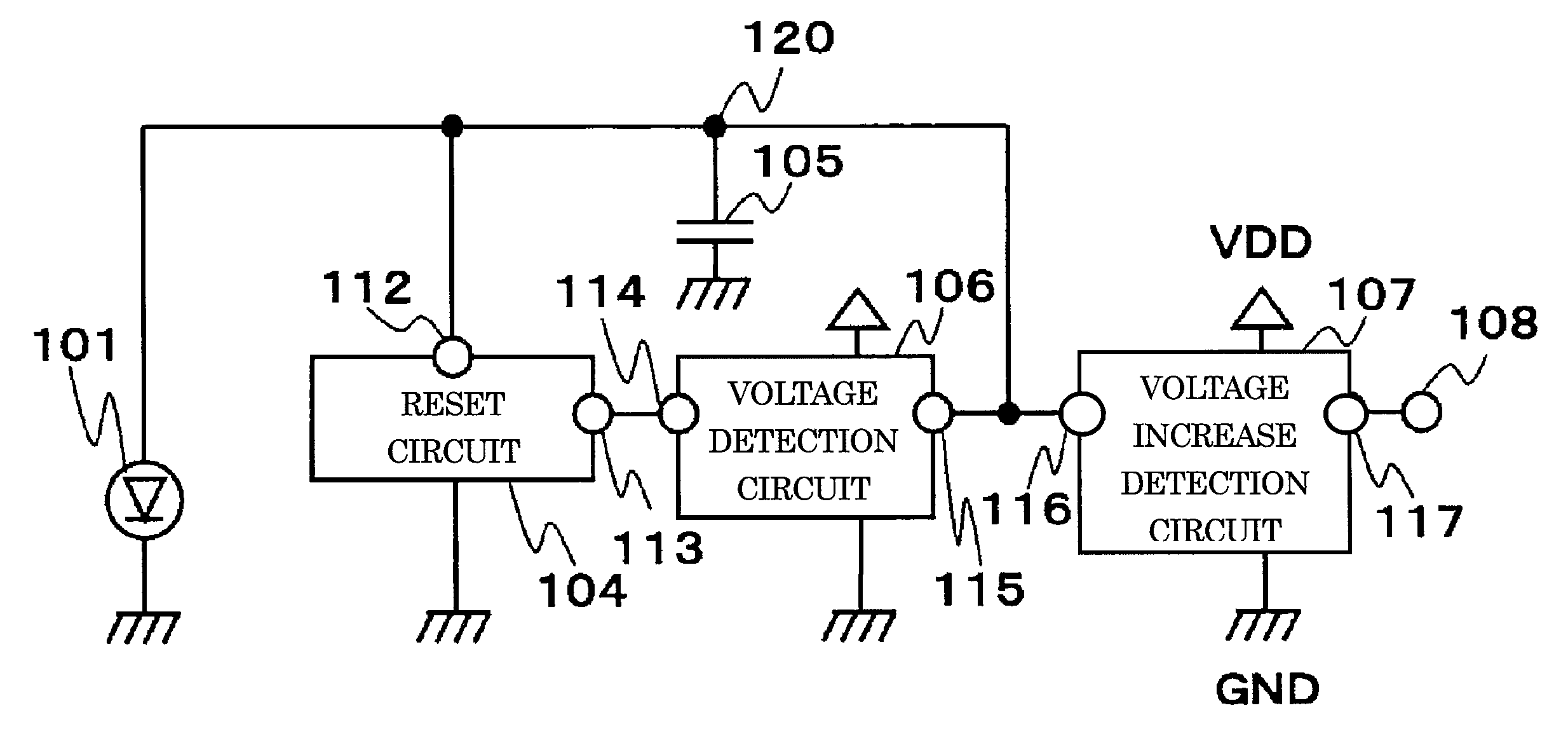
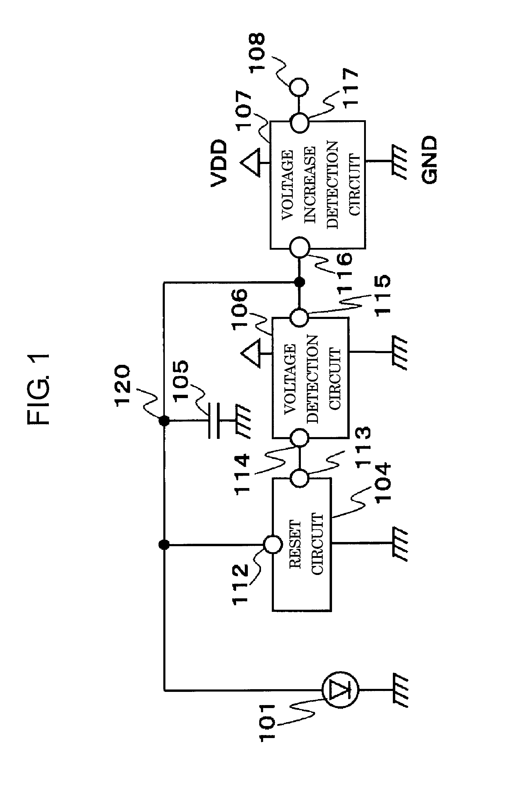
[0021]FIG. 1 is a block diagram illustrating a light receiving circuit according to an embodiment of the present invention.

[0022]The light receiving circuit according to this embodiment includes a photodiode 101, a reset circuit 104, a capacitor 105, a voltage detection circuit 106, and a voltage increase detection circuit 107.

[0023]The photodiode 101 has an N-type terminal connected to a GND terminal and a P-type terminal connected to a node 120. The reset circuit 104 has a reset terminal 112 connected to the node 120 and an input terminal 113 connected to an output terminal 114 of the voltage detection circuit 106. The capacitor 105 has one terminal connected to the node 120 and the other terminal connected to the GND terminal. The voltage detection circuit 106 has an input terminal 115 connected to the node 120. The voltage increase detection circuit 107 has an input terminal 116 connected to the node 120 and an output terminal 117 connected to an output terminal 108.

[0024]The ph...


PUM


Abstract

The light receiving circuit includes: a photoelectric conversion element for causing a current corresponding to an amount of incident light to flow to a node; a voltage detection circuit for outputting a detection signal when a voltage of the node becomes equal to or higher than a first voltage; a reset circuit for causing, when the detection signal of the voltage detection circuit is input, the current of the photoelectric conversion element to flow to a GND terminal so that the voltage of the node becomes a second voltage lower than the first voltage, and for holding this state when the detection signal is no longer input; and a voltage increase detection circuit for detecting a fluctuation in the voltage of the node and outputting a detection result.

Description

RELATED APPLICATIONS[0001]This application claims priority under 35 U.S.C. §119 to Japanese Patent Application No. 2013-055356 filed on Mar. 18, 2013, the entire content of which is hereby incorporated by reference.BACKGROUND OF THE INVENTION[0002]1. Field of the Invention[0003]The present invention relates to a light receiving circuit for detecting a change in amount of light, and more particularly, to a light receiving circuit capable of stable detection of a change in amount of light regardless of ambient light conditions.[0004]2. Description of the Related Art[0005]Light receiving circuits are used for receiving optical signals in infrared remote control communications or visible light communications and used for photointerrupters, distance sensors, and the like. The light receiving circuit needs to function to detect an abrupt change in amount of light generated when an LED or the like is turned on without detecting a slow change in amount of light generated when a person moves...

Claims


Application Information

Patent Timeline
Patent Type & Authority Patents(United States)
IPC IPC(8): H03K5/153H03K5/24
CPCH03K5/153H03K5/2472G01J1/44
Inventor UTSUNOMIYA, FUMIYASU
Owner ABLIC INC
Why Eureka
Eureka Blog
Learn More