
Illuminating device for an operating microscope

a technology of illumination device and operating microscope, which is applied in the field of illumination device for operating microscope, can solve the problems of unavoidable minimum angles between the optical axis of a main objective or the observation beam path and the illuminating beam path, and the red reflex is very easy for the main surgeon to see, but cannot be seen satisfactorily by the co-observer, etc., and achieves the effect of compact design and cheap production

Active Publication Date: 2015-01-27
LEICA MICROSYSTEMS (SCHWEIZ) AG
View PDF6 Cites 4 Cited by
  • Summary
  • Abstract
  • Description
  • Claims
  • Application Information

AI Technical Summary

Benefits of technology

The present invention provides an illuminating device for an operating microscope that is simple, compact, and affordable. The device has two semitransparent deflector elements that provide an optimised red reflex for both the main observer and the assistant. This design minimizes the number of deflector elements needed and ensures that the red reflex is of the same quality for both observers. Additionally, the illuminating beam paths are designed to act only on one deflector element to prevent undesirable light reflexes and crosstalk between individual channels of the microscope. Overall, this invention provides a compact stereomicroscope that is easy to use and has improved visual acuity.

Problems solved by technology

Operating microscopes which are configured with two pairs of stereoscopic observation beam paths for a first observer (main surgeon) and a second observer (assistant), respectively, often have the disadvantage that the red reflex is very easy for the main surgeon to see but cannot be seen satisfactorily by the co-observer.
This has an adverse effect on stereoscopic viewing.
Because of the total mirror finish these deflector elements cannot be placed in the observation beam paths, which means that certain minimum angles between the optical axis of a main objective or the observation beam paths and the illuminating beam paths are unavoidable.

Method used


Image

  • Illuminating device for an operating microscope
  • Illuminating device for an operating microscope
  • Illuminating device for an operating microscope

Examples


Embodiment Construction

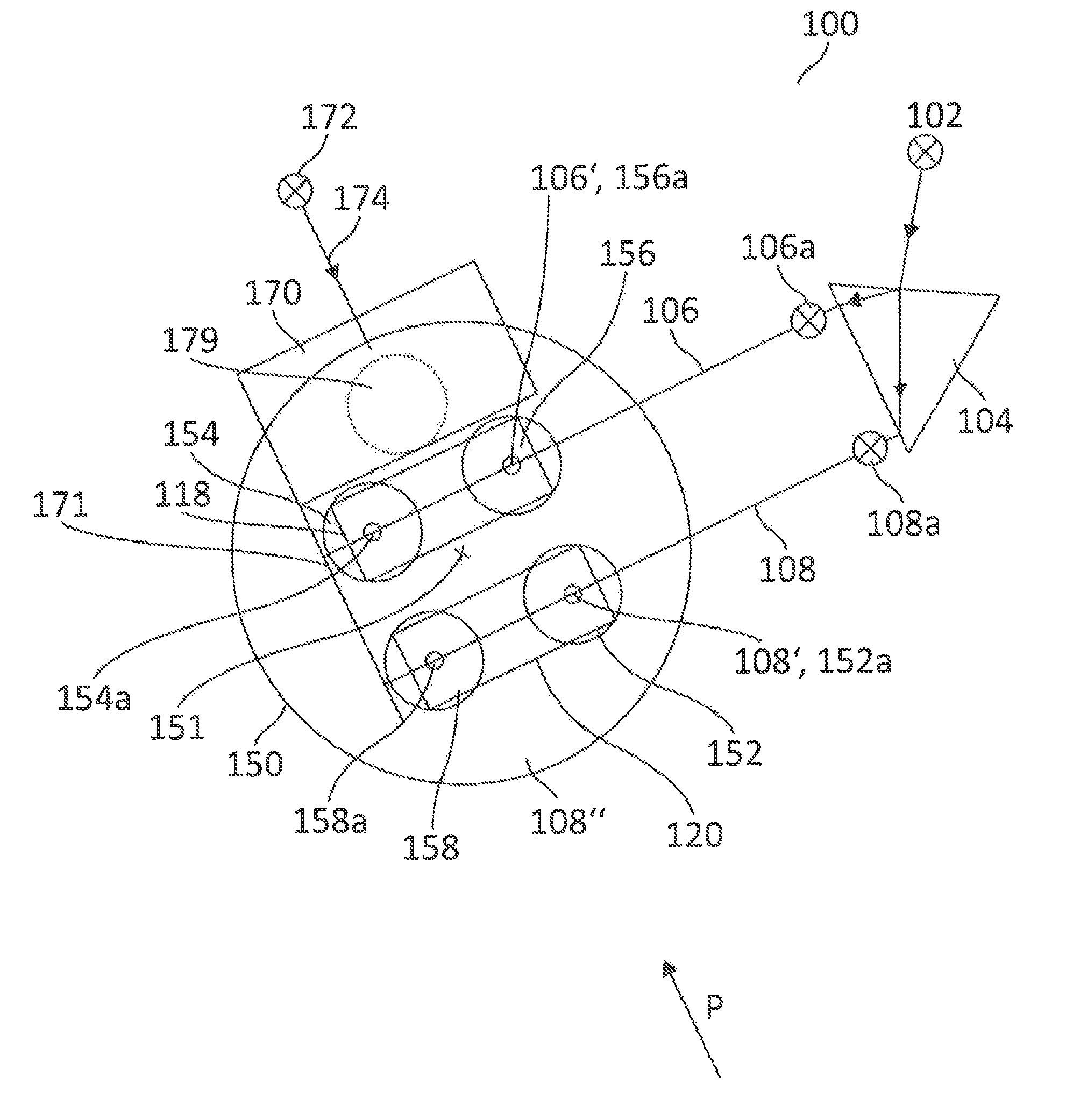
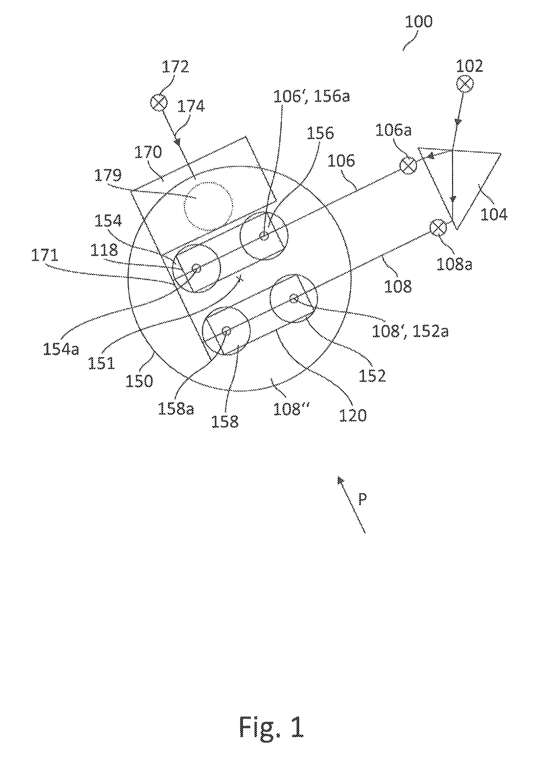
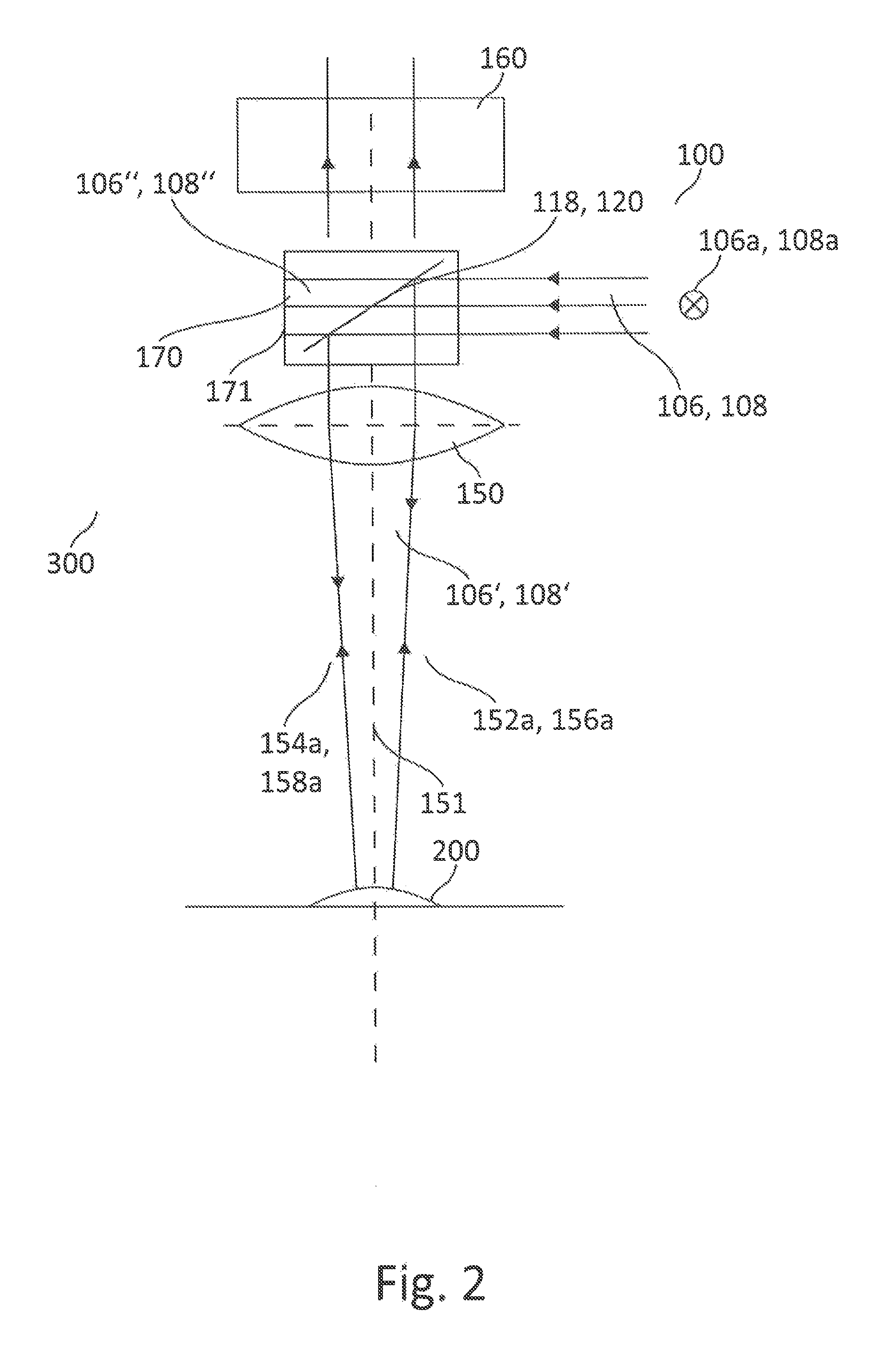
[0034]In FIGS. 1 and 2, a preferred embodiment of the illuminating device according to the invention, comprising a main objective 150 and, downstream thereof, a magnification system (including the requisite tubes and eyepieces) 160 of a microscope 300, is generally designated 100.

[0035]The microscope 300 is an operating stereomicroscope which provides two observation beam paths 152, 154 for a main surgeon and two further observation beam paths 156, 158 for an assistant. The observation beam paths running in corresponding observation channels are represented in FIG. 1 as circles and in FIG. 2 by means of the observation axes 152a, 154a, 156a, 158a associated therewith. There is no need to go into detail about specific items of equipment (such as e.g. lenses and zoom systems) for providing four such observation channels within the scope of the present invention relating to an illuminating device.

[0036]The illuminating device 100 according to the invention first of all has a light sour...


PUM


Abstract

The present invention relates to an illuminating device for an operating microscope including two observation beam paths for a first observer and two observation beam paths for a second observer. An illuminating system provides two parallel illuminating beam paths and a deflecting device, for deflecting the parallel illuminating beam paths onto an object that is to be observed. The deflecting device includes a first semitransparent deflector element which is associated with a first observation beam path of the first observer and a first observation beam path of the second observer, and a second semitransparent deflector element, which is associated with a second observation beam path of the first observer and a second observation beam path of the second observer. The first illuminating beam path acts exclusively on the first deflector element and the second illuminating beam path acts exclusively on the second deflector element.

Description

CROSS REFERENCE TO RELATED APPLICATIONS[0001]This application claims priority of the German patent application 10 2010 003 295.6 filed Mar. 25, 2010, the entire disclosure of which is incorporated by reference herein.FIELD OF THE INVENTION[0002]The present invention relates to an illuminating device for an operating microscope of a type having two observation beam paths for a first observer (main surgeon) and two observation beam paths for a second observer (assistant), and to a stereomicroscope of a type having a main objective and a magnification system downstream from the main objective.BACKGROUND OF THE INVENTION[0003]Illuminating devices for operating microscopes generally use an illuminating beam path which is at an angle in the region of about 6° to the observation beam path (so-called 6° illumination). This avoids the undesirable shadowing which would occur at larger angles between the observation beam path and the illuminating beam path.[0004]Eye surgery places additional s...

Claims


Application Information

Patent Timeline
Patent Type & Authority Patents(United States)
IPC IPC(8): G02B21/22A61B19/00G02B21/00G02B27/14
CPCG02B21/0012A61B19/5223G02B21/22A61B19/5202G02B27/144A61B90/20A61B90/30
Inventor KUSTER, MANFREDSUHNER, HEINZ
Owner LEICA MICROSYSTEMS (SCHWEIZ) AG
Learn More