Filter holder for correlative particle analysis

a filter holder and correlative particle technology, applied in the field of filter holder for correlative particle analysis, can solve the problems of insufficient cleaning, large replacement cost, particle scratching of glass panel,

Active Publication Date: 2015-01-27
CARL ZEISS MICROSCOPY GMBH
View PDF10 Cites 1 Cited by
  • Summary
  • Abstract
  • Description
  • Claims
  • Application Information

AI Technical Summary

Benefits of technology

[0005]Proceeding from the described disadvantages of the solutions of the prior art, the problem addressed by the invention is that of further developing a filter holder for correlative particle analysis such that, with the advantages of the solutions of the prior art, a cost-effective, quick and reproducible particle analysis on a filter fastened in the orientation of one plane can be performed and verified.
[0012]Due to the planar stretching of the filter, the entire filter surface can be observed without frequent refocusing. This saves significant time when compared to solutions without a plane filter position.
[0014]A coordinate system which is marked on the filter holder, and which can also be transported when devices are changed, allows for a precise relocalization of individual particles.
[0017]This type of fastening of the filter thus ensures a secure clamping and tensioning in the plane without causing damage to the filter.

Problems solved by technology

This solution is disadvantageous because over time, particularly during the cleaning process, the particles scratch the glass panel which then has to be replaced at great cost.
It is further disadvantageous because particles from the filter remain on the glass panel when said panel is removed and a reexamination of the filters yields different results than the results obtained from the first observation.
Furthermore, insufficient cleaning poses the risk of adhering particles contaminating the filter to be examined next and thus falsifying the measurement result.
However, it is most disadvantageous that filters covered with a glass panel cannot be imaged with an electron microscope and also do not allow for an elemental analysis with X-ray spectroscopy.
This is disadvantageous because the filter material becomes uneven due to the drying process after filtering.

Method used


Image

  • Filter holder for correlative particle analysis
  • Filter holder for correlative particle analysis
  • Filter holder for correlative particle analysis

Examples


Embodiment Construction

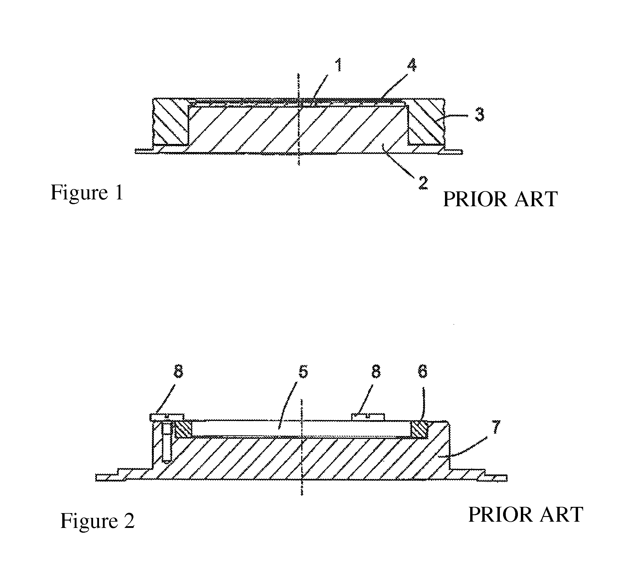
[0033]FIG. 1 shows a solution of the prior art with a filter 1, which is arranged on a plane filter support 2 and fastened to a glass panel 4 by the weight of a frame 3, wherein the fastening is also possible with the use of screw connections or spring elements. As already described in the prior art, this solution is disadvantageous because due to frequent filter changes, particularly during the cleaning process, the particles scratch the glass panel which then has to be replaced at great cost.

[0034]However, it is most disadvantageous that filters covered with a glass panel cannot be imaged with an electron microscope and also do not allow for an elemental analysis with X-ray spectroscopy.

[0035]FIG. 2 describes a further solution according to the prior art which shows a filter 5 positioned at the periphery with a clamping ring 6 on a filter support 7. The clamping ring 6 is commonly fastened vertically using screw connections 8.

[0036]As initially described, this solution is disadvan...


PUM

PropertyMeasurementUnit
imaging microscopyaaaaaaaaaa
circumferenceaaaaaaaaaa
tension forceaaaaaaaaaa

Abstract

A filter holder for correlative particle analysis during imaging microscopy methods or methods of the elemental analysis including a receiving element with a filter support and a fastening unit. The plane filter support is designed as pressure piece and is movably arranged in the receiving element to be movable at a right angle to the surface of the filter for the purpose of tensioning the filter. The fastening unit includes a clamping element which encloses the filter at the circumference of the filter and is held by a tensioning element which is supported in the receiving element.

Description

CLAIM TO PRIORITY[0001]This application claims the benefit of German Patent Application DE 102011117134.0 filed Oct. 21, 2011 the entire contents of which are incorporate by reference herein.FIELD OF THE INVENTION[0002]The invention relates to a filter holder for correlative particle analysis during imaging microscopy methods or methods of elemental analysis, comprising a receiving element with a filter support and a fastening unit.BACKGROUND[0003]Filter holders with a glass panel are known. In this prior art, a glass panel ground to optical quality and usually coated with an antireflection layer presses the filter made of paper or plastic fabric level or flat onto the filter holder. This is caused either by the weight of the glass panel and the frame, by screw connection, or spring force. This solution is disadvantageous because over time, particularly during the cleaning process, the particles scratch the glass panel which then has to be replaced at great cost. It is further disad...

Claims


Application Information

Patent Timeline
Patent Type & Authority Patents(United States)
IPC IPC(8): G02B21/26G01N1/28G01N15/00G01N15/06G02B21/34
CPCG02B21/34G01N1/2813G01N15/0625G01N2015/0042
Inventor HEISE, HEINOKOHLHAAS, ULRICH
Owner CARL ZEISS MICROSCOPY GMBH
Why Eureka
Try Eureka